20033283
28
Start-up, calibration and operation of the burner
7.5 Burner starting (gas operation)
Close the control devices and set:
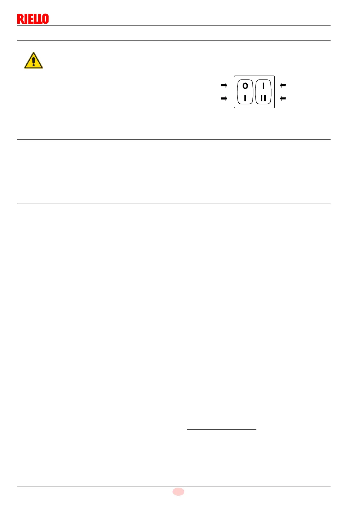
switch 1)(Fig. 35) to "burner ON" position
switch 2)(Fig. 35) to "1
st
stage" position
As soon as the burner starts make sure that the lamps or testers
connected to the solenoids, or pilot lights on the solenoids them-
selves, indicate that no voltage is present.
If voltage is present, then immediately stop the burner and check
electrical connections.
7.6 Burner firing (gas operation)
Having completed the checks indicated in the previous heading,
the burner should fire. If the motor starts but the flame does not
appear and the control box goes into lock-out, reset and wait for
a new firing attempt.
If firing is still not achieved, it may be that gas is not reaching the
combustion head within the safety time period of 3 seconds.
In this case increase gas firing delivery.
The arrival of gas at the sleeve is indicated by the U-type manom-
eter (Fig. 34).
Once the burner has fired, now proceed with global calibration
operations.
7.7 Burner calibration (gas operation)
The optimum calibration of the burner requires an analysis of the
flue gases at the boiler outlet.
Adjust successively:
–2
nd
stage burner output
–1
st
stage burner output
– Firing output
– Air pressure switch
– Minimum gas pressure switch
7.7.1 2
nd
stage output
2
nd
stage output of the burner must be set within the firing rate
range shown at page 11.
Set switch 2)(Fig. 35) to the 2
nd
stage position: the servomotor
will open the air gate valve at the previously set value for oil and
will control the opening of the 2
nd
stage gas valve VR2.
Gas calibration
Adjust gas delivery to the amount of air.
– If delivery needs to be reduced, diminish outlet gas pressure
and, if it is already very low, slightly close 2
nd
stage adjust-
ment valve VR2.
– If delivery needs to be increased, increase outlet gas pres-
sure.
7.7.2 1
st
stage output
Burner power in 1
st
stage operation must be selected within the
firing rate range shown at page 11.
Set the switch 2)(Fig. 35) to the 1
st
stage position: the servomotor
will close the air gate valve at the previously set value for oil and
will control the opening of the 1
st
stage gas valve VR1.
Adjusting gas delivery
Adjust gas delivery to the amount of air by adjusting the 1
st
stage
gas valve VR1.
7.7.3 Firing output
According to EN 676 Regulations:
Burners with MAX output up to 120 kW
Firing can be performed at the maximum operation output level.
Example:
– max. operation output : 120 kW
– max. firing output : 120 kW
Burners with MAX output above 120 kW
Firing must be performed at a lower output than the max. opera-
tion output. If the firing output does not exceed 120 kW, no calcu-
lations are required. If firing output exceeds 120 kW, the
regulations prescribe that the value be defined according to the
control box safety time “ts”:
– for ts = 2s, firing output must be equal to or lower than 1/2 of
max. operation output;
– for ts = 3s, firing output must be equal to or lower than 1/3 of
max. operation output.
Example:
MAX operation output of 600 kW.
Firing output must be equal to or lower than:
– 300 kW con ts = 2s
– 200 kW con ts = 3s
In order to measure the firing output:
Extract the UV cell 14)(Fig. 5 at page 12) (the burner will
ignite and lock-out at the end of a safety period).
Perform 10 firings with consecutive lock-outs.
On the meter read the quantity of gas burned. This quantity
must be equal to or lower than the quantity given by the for-
mula:
Example for G 20 (10 kWh/Nm
3
):
max. operation output: 600 kW corresponding to 60 Nm
3
/h.
After 10 firings with lock-outs, the delivery read on the meter must
be equal to or lower than: 60 : 360 = 0.166 Nm
3
.
Firing output must be adjusted on the gas valve throttle.
It is advisable to first set the burner for operating
on oil and then for gas.
Execute the fuel exchange when the burner is off.
Fig. 35
Off 1
st
2
nd
12
On
Burner Stage
D469
Nm
3
/h (max. burner delivery)
360