20033283
24
Electrical system
6.1 Notes on safety for the electrical wiring
Before carrying out any maintenance, cleaning or checking oper-
ations:
If the cover is still present, remove it and proceed with the electri-
cal wiring according to the wiring diagrams.
6.2 Electrical connections
Use flexible cables according to EN 60 335-1. Regulations:
– if in PVC sheath, use at least H05 VV-F;
– if in rubber sheath, use at least H05 RR-F.
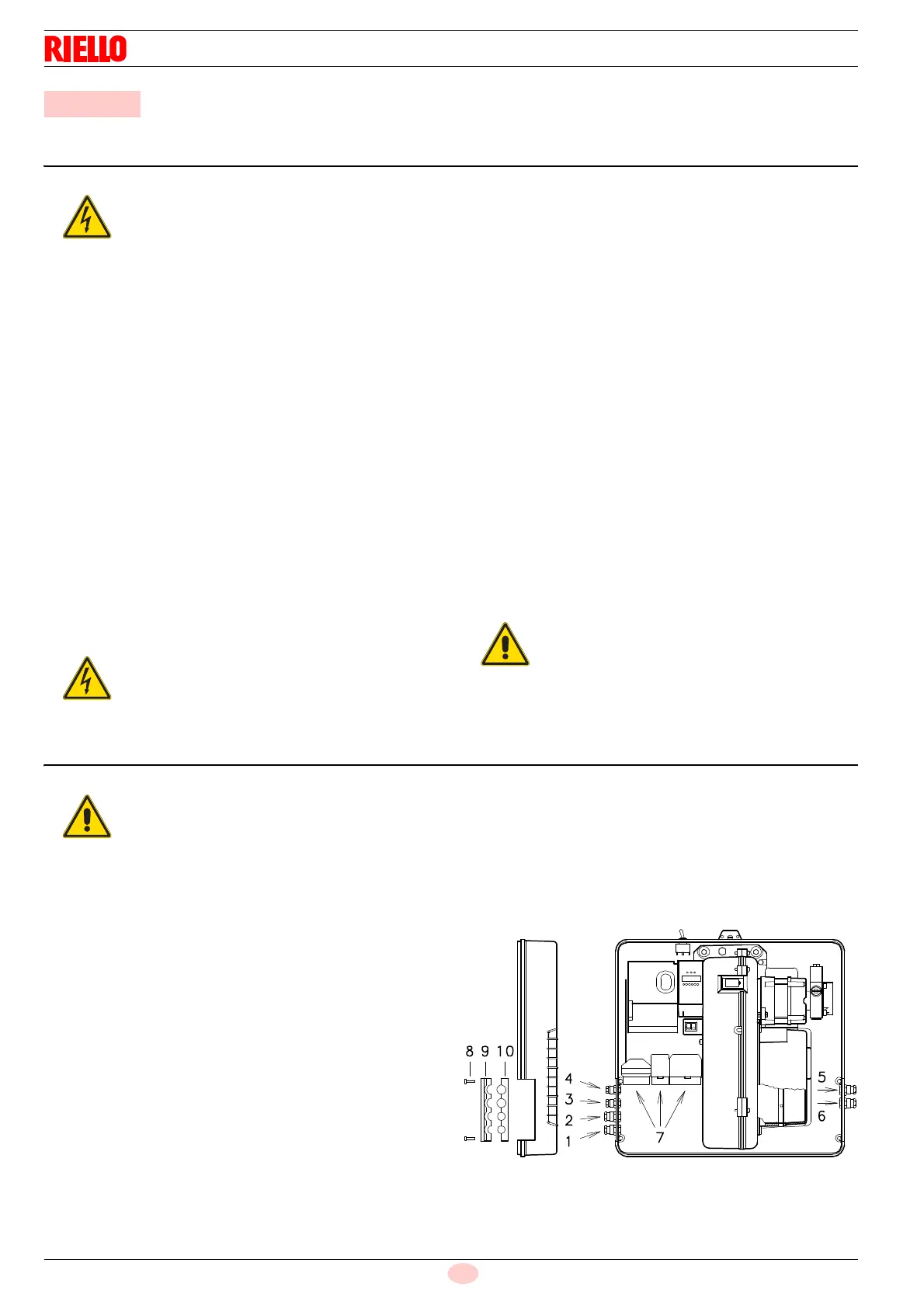
All the wires to connect to the burner plugs 7)(Fig. 26) must enter
through the supplied fairleads, which must be fitted into the rele-
vant holes in the left hand or right hand plate.
To do this, first unscrew screws 8), then split the plate into its two
parts 9) and 10) and remove the membrane press-outs from the
holes. The fairleads and hole press-outs can be used in various
ways; the following lists show one possible solution:
RLS 28 and RLS 38
1 Pg 11 Single-phase power supply
2 Pg 11 Gas valves
3 Pg 9 Remote control device TL
4 Pg 9 Remote control device TR
5 Pg 11 Gas pressure switch or gas valve leak detection con-
trol device
RLS 50
1 Pg 11 Three-phase power supply
2 Pg 11 Single-phase power supply
3 Pg 9 Remote control device TL
4 Pg 9 Remote control device TR
5 Pg 11 Gas valves
6 Pg 11 Gas pressure switch or gas valve leak detection con-
trol device
6 Electrical system
The electrical wiring must be carried out with the electrical supply disconnected.
Electrical wiring must be carried out by qualified personnel and in compliance with the regulations currently in
force in the country of destination. Refer to the wiring diagrams.
The manufacturer declines all responsibility for modifications or connections different from those shown in the wir-
ing diagrams.
Do not invert the neutral with the phase in the electrical supply line. Any inversion would cause a lockout due to fir-
ing failure.
Check that the electrical supply of the burner corresponds to that shown on the identification label and in this man-
ual.
The burners have been set for intermittent operation. This means they should compulsorily be stopped at least
once every 24 hours to enable the control box to perform checks of its own start-up efficiency. Normally the
boiler's thermostat/pressure switch ensures the stopping of the burner.
If this is not the case, it is necessary to apply in series with IN a timer switch that turns off the burner at least once
every twenty-four hours. Refer to the wiring diagrams.
The electrical safety of the device is obtained only when it is correctly connected to an efficient earthing system,
made according to current standards. It is necessary to check this fundamental safety requirement. In the event of
doubt, have the electrical system checked by qualified personnel.
The electrical system must be suitable for the maximum input power of the device, as indicated on the label and in
the manual, checking in particular that the section of the cables is suitable for the input power of the device.
For the main power supply of the device from the electricity mains:
- do not use adapters, multiple sockets or extensions;
- use an omnipolar switch, as indicated by the current safety standards.
Do not touch the device with wet or damp body parts and/or in bare feet.
Do not pull the electric cables.
disconnect the electrical supply from the burner by
means of the main system switch;
isolate the fuel supply.
Electrical wiring must be made in accordance with
the regulations currently in force in the country of
destination and by qualified personnel.
Riello S.p.A. declines all liability for modifications
or connections other than those shown on these
diagrams.