17
20033283
Installation
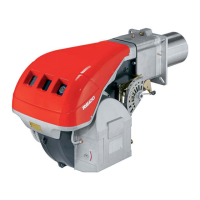
The nozzle for the 1st stage of operation is the one lying beneath
the firing electrodes (Fig. 14).
Refit the burner 4)(Fig. 15) to the slide bars 3) at approxi-
mately 100 mm from the sleeve 5) - burner positioned as
shown in Fig. 9 at page 15.
Insert the ignition electrode cables and then slide the burner
up to the sleeve so that it is positioned as shown in Fig. 15.
Refit screws 2) on slide bars 3).
Secure the burner to the sleeve by tightening screw 1) and
then refit the split pin into one of two slide bars 3).
Connect the oil pipes again by screwing on the two connec-
tors 4)(Fig. 9 at page 15).
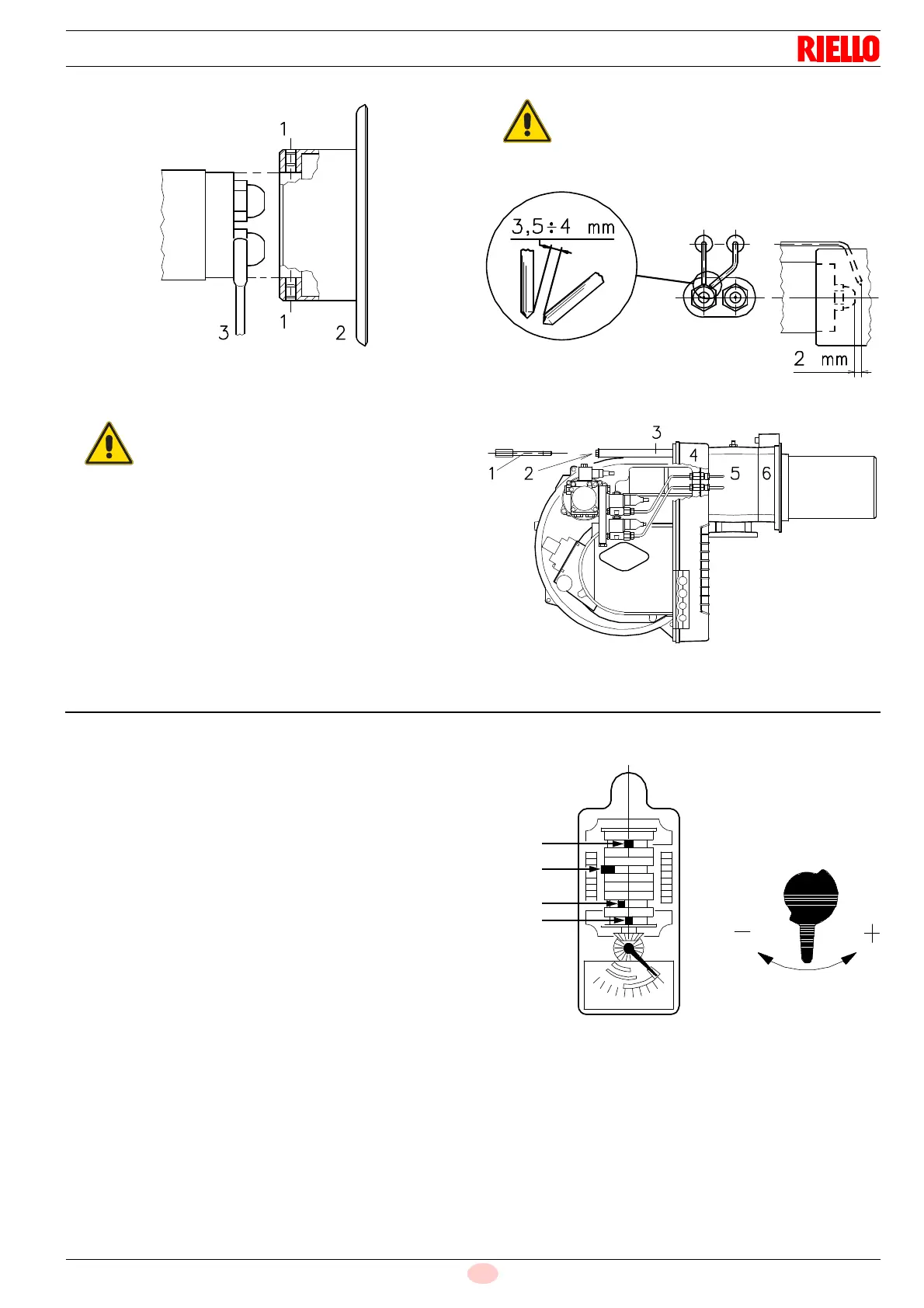
5.10 Servomotor
The servomotor (Fig. 16) adjusts the air gate valve.
The servomotor rotates through 90° in 5 seconds.
Do not alter (for the time-being) the factory setting for the 4 le-
vers. A graduated plate with 4 coloured sectors marks the lever
operation point.
Blue lever
Sets the position of the air gate valve while the burner is shut
down: air gate valve closed.
Orange lever
Sets the position of the air gate valve during 1
st
stage operation.
Red lever
Sets the position of the air gate valve during 2
nd
stage operation.
Black lever
Establishes when the 2
nd
stage gas or gas oil valve opens.
It must always operate (just) before the red lever and after the or-
ange lever.
It must not operate with the red lever as this may prevent the gas
or gas oil valve from opening at all.
It must not operate straight after the orange lever to avoid com-
bustion in the absence of air.
For gas or gas oil valve opening to approach that of 2
nd
stage air
gate valve position, rotate the black lever to the left; to delay
opening time, rotate the lever to the right.
In brief, the levers must be operated in the following sequence:
1 Blue lever
2 Orange lever
3 Black lever
4 Red lever
Make sure that the electrodes are positioned as
shown in Fig. 14.
When fitting the burner on the two slide bars, it is
advisable to gently draw out the high tension ca-
bles until they are slightly stretched.
Fig. 16
D1134
Blue
Orange
Black
Red
LEVER