20033283
30
Start-up, calibration and operation of the burner
7.9 Burner operation
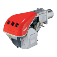
NORMAL FIRING
(n° = seconds from instant 0)
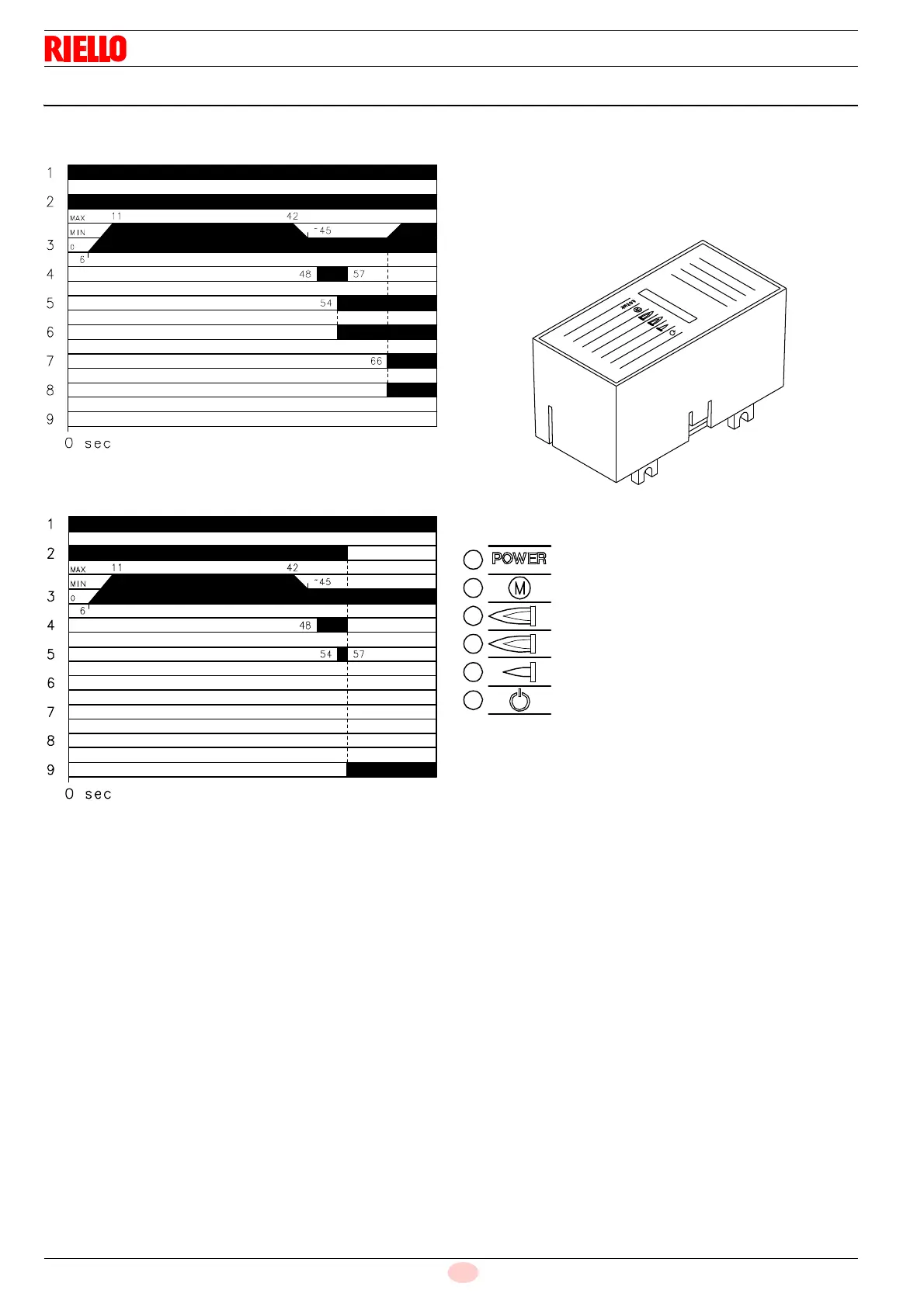
NO FIRING
Key Fig. 38 - Fig. 39
1Thermostat
2 Motor
3 Air gate valve
4 Ignition transformer
5 First valve
6 First flame
7 Second valve
8 Second flame
9 Lock-out
7.9.1 Burner flame goes out during operation
If the flame should accidentally go out during operation, the burn-
er will lock out within 1s.
7.9.2 Led panel
The burners are fitted with an electronic device, which supplies a
diagnostic of burner status.
It provides 6 data items signalled by the leds lighting up. See
Fig. 40.
Key Fig. 40
D478
Power on
Fan motor blocked (red colour)
Burner lock-out (red colour)
2
nd
stage operation
1
st
stage operation
Burner operating