20033283
12
Technical description of the burner
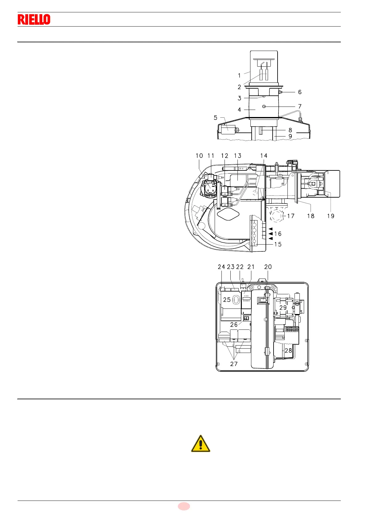
4.9 Burner description
1 Combustion head
2 Ignition electrodes
3 Screw for combustion head adjustment
4 Sleeve
5 Minimum air pressure switch (differential operating type)
6 Air pressure test point
7 Gas pressure test point and head fixing screw
8 Screw securing fan to sleeve
9 Slide bars for opening the burner and inspecting the com-
bustion head
10 Pump
11 Safety solenoid valve
12 1
st
and 2
nd
stage valves
13 Servomotor.
When the burner is stopped the air gate valve will be com-
pletely closed to reduce heat loss due to the flue draught,
which tends to draw air from the fan air inlet.
14 Cell UV
15 Plate with four hole knock-outs for flexible hoses and electri-
cal cable routing.
16 Air inlet to fan
17 Gas input pipework
18 Boiler mounting flange
19 Flame stability disk
20 Flame inspection window
21 LED PANEL
22 OIL /GAS selector
23 Fan motor contactor and thermal cut-out with reset button
(RLS 50 three-phase)
24 Fan motor capacitor (RLS 28 - RLS 38)
25 Control box with lock-out pilot light and lock-out reset button
26 Two switches:
- one “burner off - on”
- one for “1
st
- 2
nd
stage operation”
27 Plugs for electrical connections
28 Air gate valve
29 Pump motor
Two types of burner failure may occur:
Control box lock-out:
if the control box 25) push-button lights up, it indicates that the
burner is in lock-out. To reset, press the push-button.
Motor trip (RLS 50 three-phase):
Release by pressing the push-button on thermal cut-out 23).
4.10 Standard equipment
1 - Gas train flange
1 - Flange gasket
4 - Flange fixing screws (M8x25)
1 - Thermal insulation screen
4 - Screws (M8x25) to secure the burner flange to the boiler
5 - Fairleads for electrical connections
(RLS 28-38 single phase)
6 - Fairleads for electrical connections (RLS 50 three phase)
2 - Hoses
2 - Nipples for hoses with gaskets
1 - KIT for LPG operation
1 - Label for LPG operation
1 - Instruction booklet
1 - Spare parts list
In case of use with gas oil containing up to 10%
Bio blend, it will be essential to use flexible oil
lines suitable for bio fuel use.
Please contact Riello for further information.