15
20033283
Installation
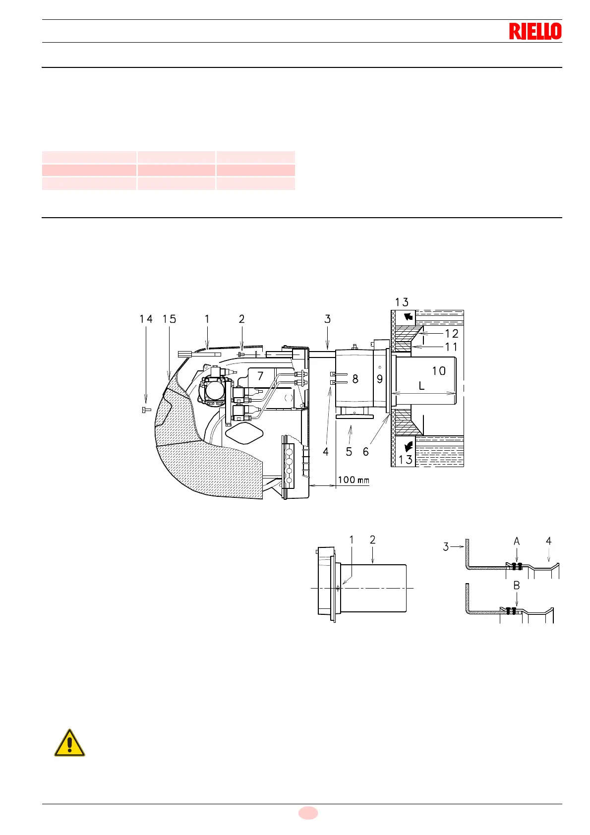
5.7 Blast tube length
The length of the blast tube must be selected according to the in-
dications provided by the manufacturer of the boiler, and in any
case it must be greater than the thickness of the boiler door com-
plete with its fettling.
The range of lengths available, L (mm), is as follows:
For boilers with front flue passes 13)(Fig. 9) or flame inversion
chambers, protective fettling in refractory material 11) must be in-
serted between the boiler fettling 12) and the blast tube 10).
This protective fettling must not compromise the extraction of the
blast tube.
For boilers having a water-cooled front the refractory fettling 11)-
12)(Fig. 9) is not required unless it is expressly requested by the
boiler manufacturer.
5.8 Securing the burner to the boiler
Detach the combustion head from the burner:
disconnect the oil pipes by unscrewing the two connectors
4)(Fig. 9).
Remove screw 14) and withdraw the cover 15).
Remove the screws 2) from the slide bars 3).
Remove screw 1) and pull the burner back on slide bars 3)
by about 100 mm.
Disconnect the electrode wires and then pull the burner
completely off the slide bars, after removing the split pin from
the slide bar 3).
5.8.1 Combustion head calibration
At this point check, for model RLS 50, whether the maximum de-
livery of the burner in 2
nd
stage operation is contained in area A
or in area B of the firing rate. See page 11.
If it is in area A then no operation is required.
If, on the other hand, it is in area B:
unscrew the screws 1)(Fig. 10) and disassemble the blast
tube 2).
Move the fixing of the rod 3) from position A to position B,
thereby causing the shutter 4) to retract.
Now refit the blast tube 2) and the screws 1).
Once this operation has been carried out (if it was required), se-
cure the flange 9)(Fig. 9) to the boiler plate, interposing the ther-
mal insulating screen 6) supplied with the burner.
Use the 4 screws, also supplied with the unit, after first protecting
the thread with an anti-locking product.
Blast tube 10)(Fig. 9) Short Long
RLS 28 191 326
RLS 38 201 336
RLS 50 216 351
The seal between burner and boiler must be air-
tight.