23
20033283
Installation
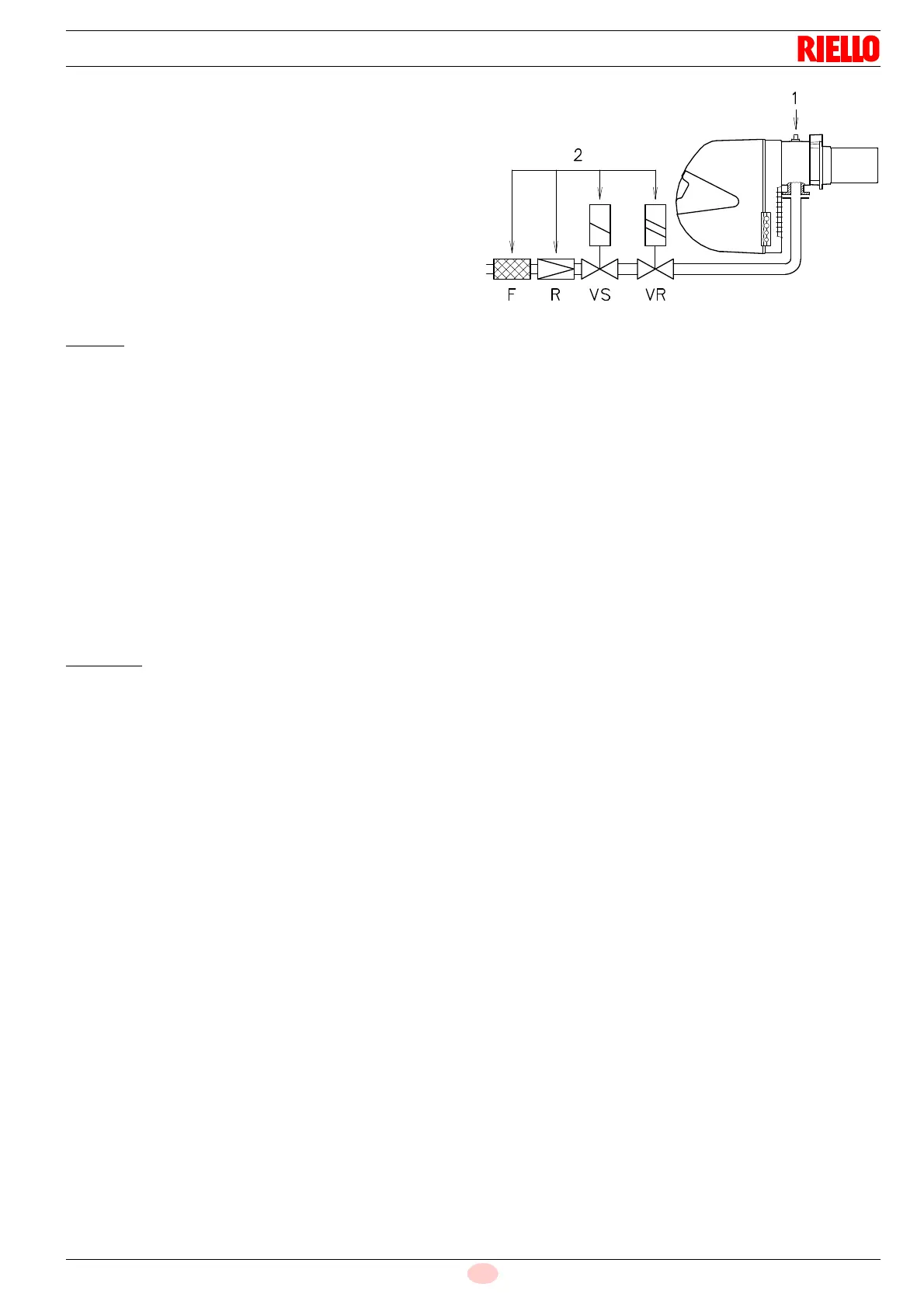
Gas pressure measured at test point 1)(Fig. 25), with:
– Combustion chamber at 0 mbar
– Burner operating in 2nd stage
– Gas G20 (methane) - G31 (propane)
Column 2 (Tab. K)
Pressure loss of gas train 2)(Fig. 25) with gas G20 includes:
– adjustment valve VR
– safety valve VS (both fully open)
– pressure governor R
– filter F
With: propane G31 PCI 27 kWh/Nm
3
(23,2 Mcal/Nm
3
) multiply
values of column 2 by 0,41.
Calculate the approximate 2
nd
stage output of the burner thus:
– subtract the combustion chamber pressure from the gas
pressure measured at test point 1)(Fig. 25).
– Find the nearest pressure value to your result in column 1 of
the Tab. K for the burner in question.
– Read off the corresponding output on the left.
Example - RLS 28
•2
nd
stage operation
• Natural gas G20 PCI 10 kWh/Nm
3
• Gas pressure at test point 1)(Fig. 25) = 9.3 mbar
• Pressure in combustion chamber = 2 mbar
9,3 - 2 = 7.3 mbar
A 2
nd
stage output of 210 kW shown in Tab. K RLS 28 corre-
sponds to 7.3 mbar pressure, column 1, gas G20.
This value serves as a rough guide, the effective delivery must be
measured at the gas meter.
To calculate the required gas pressure at test point 1)(Fig. 25),
set the output required from the burner in 2
nd
stage operation:
– find the nearest output value in the Tab. K for the burner in
question.
– Read off the pressure at test point 1)(Fig. 25) on the right in
column 1.
– Add this value to the estimated pressure in the combustion
chamber.
Example - RLS 28
• Required burner output in 2
nd
stage operation: 210 kW
• Natural gas G20 PCI 10 kWh/Nm
3
• Gas pressure at burner output of 210 kW,
column 1, G 20 = 7.3 mbar
• Pressure in combustion chamber = 2 mbar
7.3 + 2 = 9.3 mbar
pressure required at test point 1)(Fig. 25).