20167399
10
Technical description of the burner
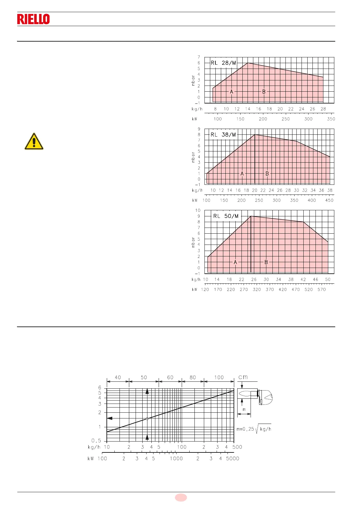
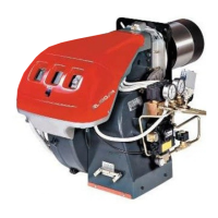
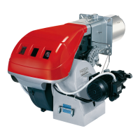
4.8 Firing rate
During operation, burner output varies between:
a MINIMUM OUTPUT: area A
a MAXIMUM OUTPUT: area B
Diagrams:
Horizontal axis: burner output
Vertical axis: pressure in combustion chamber
The work point is found by drawing a vertical line from the
required output and an horizontal line from the corresponding
pressure in the combustion chamber.
The intersection of these two lines is the work point which must
lie within area A for the MINIMUM output and area B for the
MAXIMUM output.
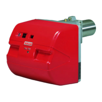
4.9 Test boiler
The firing rate was measured in special test boilers, according to
the procedures prescribed in EN 267 regulations.
In (Fig. 4) you can see the diameter and length of the test
combustion chamber.
Example
output 35 kg/hour: diameter = 50 cm; length = 1.5 m.
If the burner were to burn in a much smaller commercial
combustion chamber, preliminary testing should be carried out.
The firing rate value (Fig. 3) has been obtained
considering an ambient temperature of 20 °C, an
atmospheric pressure of 1013 mbar (approx. 0 m
a.s.l.), and with the combustion head adjusted as
shown on page 18.
Fig. 3
D853
Thermal power
Thermal power
Thermal power
Pressure in the combustio
chamber
Pressure in the combustion
chamber
Pressure in the combustion
chamber
D454
Fig. 4
length m
Combustion chamber