20167399
16
Installation
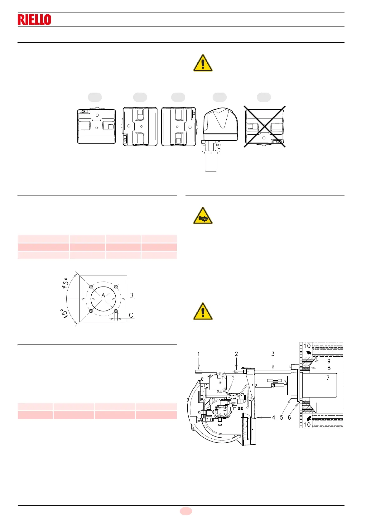
5.6 Operating position
The burner is set up to operate only in positions 1, 2, 3 and 4.
Installation 1 is preferable, as it is the only one that allows the
maintenance operations as described in this manual.
Installations 2, 3 and 4 allow operation but make maintenance
and inspection of the combustion head more difficult, page 29.
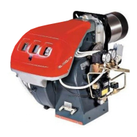
5.7 Boiler plate
Pierce the closing plate of the combustion chamber, as in
(Fig. 11). The position of the threaded holes can be marked using
the thermal insulation screen supplied with the burner.
Tab. G
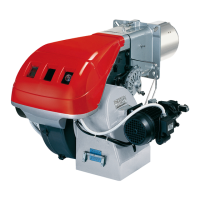
5.8 Blast tube length
The length of the blast tube must be selected according to the
indications provided by the manufacturer of the boiler, and in any
case it must be greater than the thickness of the boiler door
complete with its fettling.
The range of lengths available, L (mm), is as follows:
For boilers with front flue passes 10)(Fig. 12) or flame inversion
chambers, a protection in heat-resistant material 8) must be
inserted between the boiler refractory 9) and the blast tube 7).
This protection must not compromise the extraction of the blast
tube.
For boilers with a water-cooled front piece, a refractory lining 8)-
9)(Fig. 12) is not necessary, unless expressly requested by the
boiler manufacturer.
5.9 Securing the burner to the boiler
Remove blast tube 7) from the burner 4)(Fig. 12) and proceed as
follows:
Remove the screws 2) from the two slide bars 3).
Remove the screw 1) retaining the burner 4) to the flange 5).
Remove the blast tube 7) complete with flange 5) and slide
bars 3).
Fix the flange 5) to the plate of the boiler interposing the seal 6)
supplied with the unit. Use the 4 screws, also supplied, after
protecting their thread with an anti-locking product.
Any other position could compromise the correct
operation of the appliance.
The installation 5 is prohibited for safety reasons.
mm A B C
RL 28/M 160 224 M 8
RL 38/M 160 224 M 8
RL 50/M 160 224 M 8
Blast tube
7)(Fig. 12):
RL 28/M RL 38/M RL 50/M
• short 241 241 241
• long 351 351 351
Provide an adequate lifting system of the burner.
The seal between burner and boiler must be
airtight.