20167399
20
Hydraulic system
6.2 Hydraulic connections
The pumps are equipped with a by-pass that connects return line
with suction line. They are installed on the burner with the by-
pass closed by screw 6)(Fig. 21).
It is therefore necessary to connect both hoses to the pump.
The pump will break down immediately if it is run with the return
line closed and the by-pass screw inserted.
Remove plugs from suction and return connectors of the pump.
Insert the flexible hoses with the supplied seals into the
connections and screw them down.
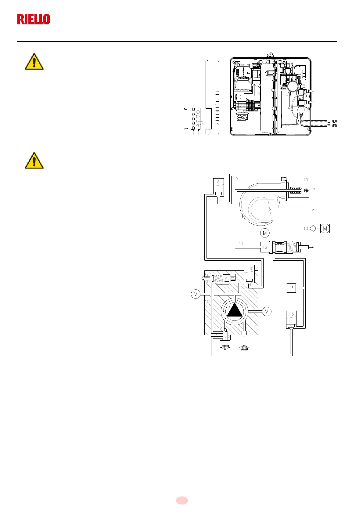
Pass the flexible hoses through the holes of the plate,
preferably on the right, (Fig. 20);
undo the screws 1), divide the insert piece into parts 2) and 3);
remove the thin diaphragm blocking the two holes 4).
Install the hoses where they cannot be stepped on or come
into contact with hot surfaces of the boiler.
Finally, connect the other end of the flexible hoses to the
nipples supplied, using two wrenches: one on the hose's
swivel fitting, for screwing, and one on the nipple, to
counteract the reaction force.
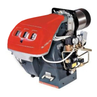
Key (Fig. 21)
6.2.1 Hydraulic circuit diagram
Make sure that the hoses to the pump supply
and return line are installed correctly.
During the installation, hoses must not be
stressed with twisting.
1 Pump suction line
2 Filter
3 Pump
4 Pressure adjuster
5 Return pipe
6 Bypass screw
7 Pump return line
8-15-16 Solenoid valves
9 Delivery line
10 Nozzle
11 Return line
12 Pressure adjustment
13 Pressure adjustment eccentric
14 Maximum oil pressure switch
M Pressure gauge
V Vacuometer connection