23
20167399
Electric system
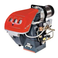
7.1.1 Supply cables and external connections
passage
All the cables to be connected to the terminal board 5)(Fig. 24) of
the burner are passed through cable grommets supplied with the
unit to be inserted in the holes of the plate, preferably on the left,
after having unscrewed the screws 6), opened the plate at parts
7) and 8) and removed the thin diaphragm that closes the holes.
The use of the cable grommets and the pre-blanked holes can be
done in different manners; for example:
RL 28/M
1 - Pg 11 Single-phase power supply
3 - Pg 9 TL remote control
4 - Pg 9 TR remote control or probe (RWF)
RL 38-50/M
Pg 11 Three-phase power supply
Pg 11 Single-phase power supply
Pg 9 TL remote control
Pg 9 TR remote control or probe (RWF)
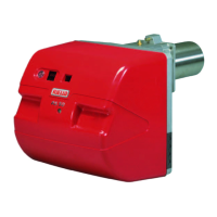
7.2 Calibration of the thermal relay
The thermal relay (Fig. 25) serves to avoid damage to the motor
due to an excessive absorption increase or if a phase is missing.
For calibration 2), refer to the table indicated in the electrical
layout (electrical wiring by the installer).
To reset, in case of an intervention of the thermal relay, press
button "RESET" 1).
The button “STOP” 3) opens the NC contact (95-96) and stops
the motor.
Insert a screwdriver in the window “TEST/TRIP” 4) and move it in
the arrow direction (to the right) to carry out the thermal relay test.
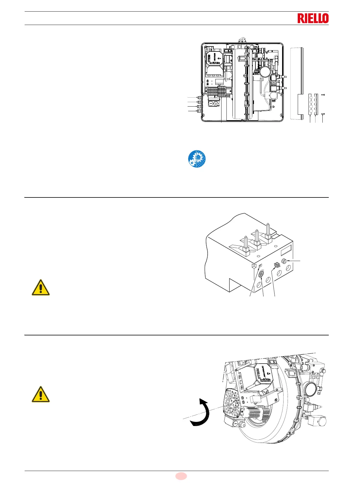
7.3 Motor rotation
As soon as the burner starts, place yourself in front of the cooling
fan of the fan motor and check that it turns anticlockwise
(Fig. 26).
If this is not the case:
put the switch of the burner to “0” (off) and wait until the
control box carries out the switching off phase.
Invert the phases on the three-phase motor power supply.
After carrying out maintenance, cleaning or
checking operations, reassemble the cover and
all the safety and protection devices of the burner.
The automatic reset can be dangerous.
This operation is not foreseen in the burner
operation.
12
3
MAN
AUTO
STOP
NO
98
97
96
95
RESET
NC
4
TEST/TRIP
Disconnect the electrical supply from the burner
by means of the system main switch.
 Loading...