33
20167399
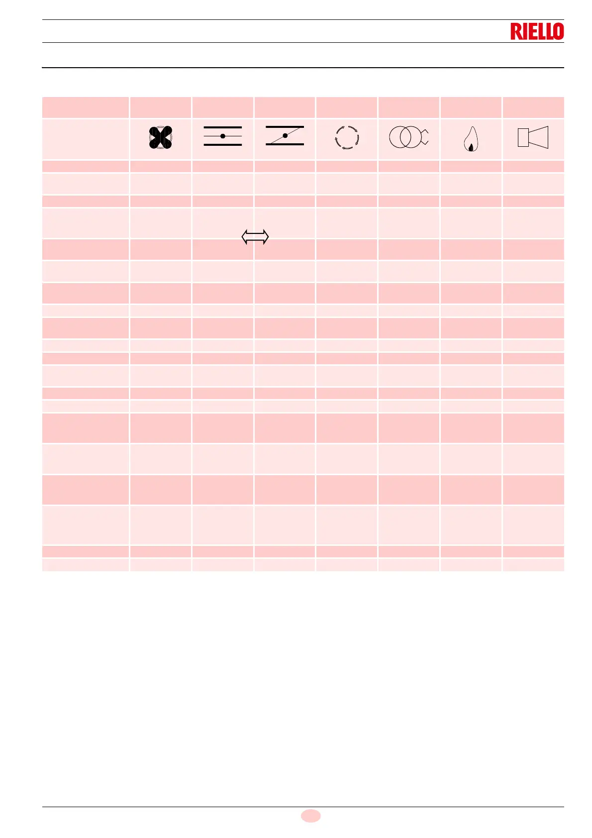
10.4 LED lamps: burner operating status
OPERATING STATUSES INDICATED BY LEDS DURING NORMAL OPERATION AND CHECK MODE
Tab. N
1. LEDs form a progress bar which indicates the Flame Signal
Power in order to orientate the sensors during commissioning
(LEDs “Grow” upwards, moving away from the Status at 20%
intervals of flame power.)
2. LEDs indicate the error or lock-out code for troubleshooting.
3. LEDs change from ON to BLINKING to OFF showing the
servomotor movement control until the position-reached
feedback is received.
See paragraph “Problems - Causes - Remedies signalled
by LED indicators” on page 34"
Operation
LED ● = ON
Fan
Damper
open
Damper
closed
Modulation Ignition Flame Status
Icon
Power OFF/ON OFF
Not ready/
Diagnostics
Green
Standby ● Green
Servomotor
movement
(Note 3)
●
OFF
Flashing
●
●
Flashing
OFF
Green
Waiting for closing Green
blinking
Green
OPEN
(before ignition)
● ● Green
Minimum
(before ignition)
● ● Green
Ignition ● ● ● Green
PTFI
● ● ●
Green
blinking
Green
MTFI ● ● ● Green
Active modulation ● ● ● Green
Minimum output
position
● ● ● Green
With flame present ● ● ● Green
Economy mode ● ● Green
Check during
maximum opening
phase
Flashing ● Yellow
Check during
minimum closing
phase
Flashing ● Yellow
Check during
ignition phase with
pilot PTFI
Flashing ● Note 1 ● Note 1 ● Note 1 ● Note 1 ● Note 1 Yellow
Check during
ignition phase with
main fuel valve
MTFI
Flashing ● Note 1 ● Note 1 ● Note 1 ● Note 1 ● Note 1 Yellow
Fault/lock-out ● Note 2 ● Note 2 ● Note 2 ● Note 2 ● Note 2 ● Note 2 Red
End of the cycle ● ● ● Green