20098824
2
GB
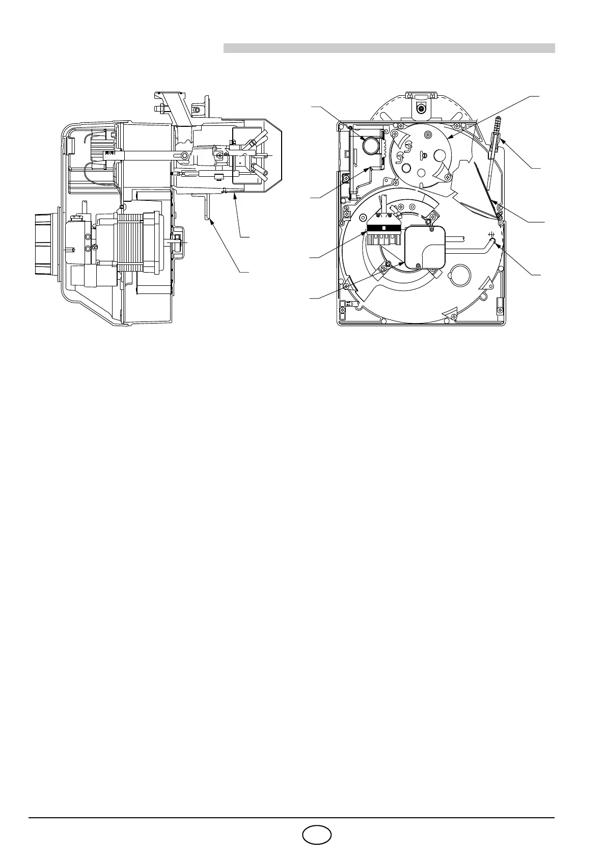
1. BURNER DESCRIPTION
One stage forced draught gas burner.
1 – Pressure switch
2 – 6 pole socket for gas train
3 – Control box with 7 pole socket
4 – Reset button with lock-out lamp
5 – Flange with insulating gasket
6 – Air damper adjustment assembly
7 – Head holder assembly
8 – Pressure test point “+”
9 – Combustion head
10 – Air damper
11 –Air intake
12 – Pressure test point “–”
13 – Gas pressure test point
1.1 BURNER EQUIPMENT
Flange with insulating gasket ........................ No. 1
Screw and nut for flange ................................ No. 1
Remote reset connection................................ No. 1
Screw and nuts for flange to be fixed to
the heat generator...................................... No. 4
Pipe for gas train ............................................ No. 1
Instructions..................................................... No. 2
Spare parts list ............................................... No. 1
1.2 ACCESSORIES (optional):
SOFTWARE DIAGNOSTIC KIT
A special kit is available that, by an optical link to a PC, shows the burner life together with operating hours,
type and number of failures, serial number, etc. To visualise the diagnostics proceed as follows:
Connect the kit supplied separately to the control box socket.
Reading of the information begins when the software programme included in the kit starts.
REMOTE RESET KIT
The burner has a remote reset kit (RS) consisting of a connection and a push-button operating at a dis-
tance of 20 metres max.
In order to install it remove the protective lock-out installed at the factory and insert the lock-out supplied
with the burner (see electrical diagram on page 10).
MULTIBLOC ROTATION KIT
There is a special kit available that can be used to install the burner turned 180°, as illustrated on page 8 in
position 5 in the section entitled "3.2 WORKING POSITION". This kit is designed to ensure the gas train
valve works properly. The kit must be installed in conformity with laws and local regulations.