20098824
12
GB
WARNING
Tighten the screws (7) completely (without locking them); then lock them with a torque wrench setting of
3 - 4 Nm.
Check there are no gas leaks from the screws during these operations.
4.3 AIR DAMPER SETTING, (fig. 8, page 11)
Do not carry out the first ignition with the air
damper lower than set point 1.
The air damper leaves the factory set on set point 1.
To vary the setting proceed as follows:
Loosen the nut (9) and the screws (8).
Once you have done, tighten the nut (9).
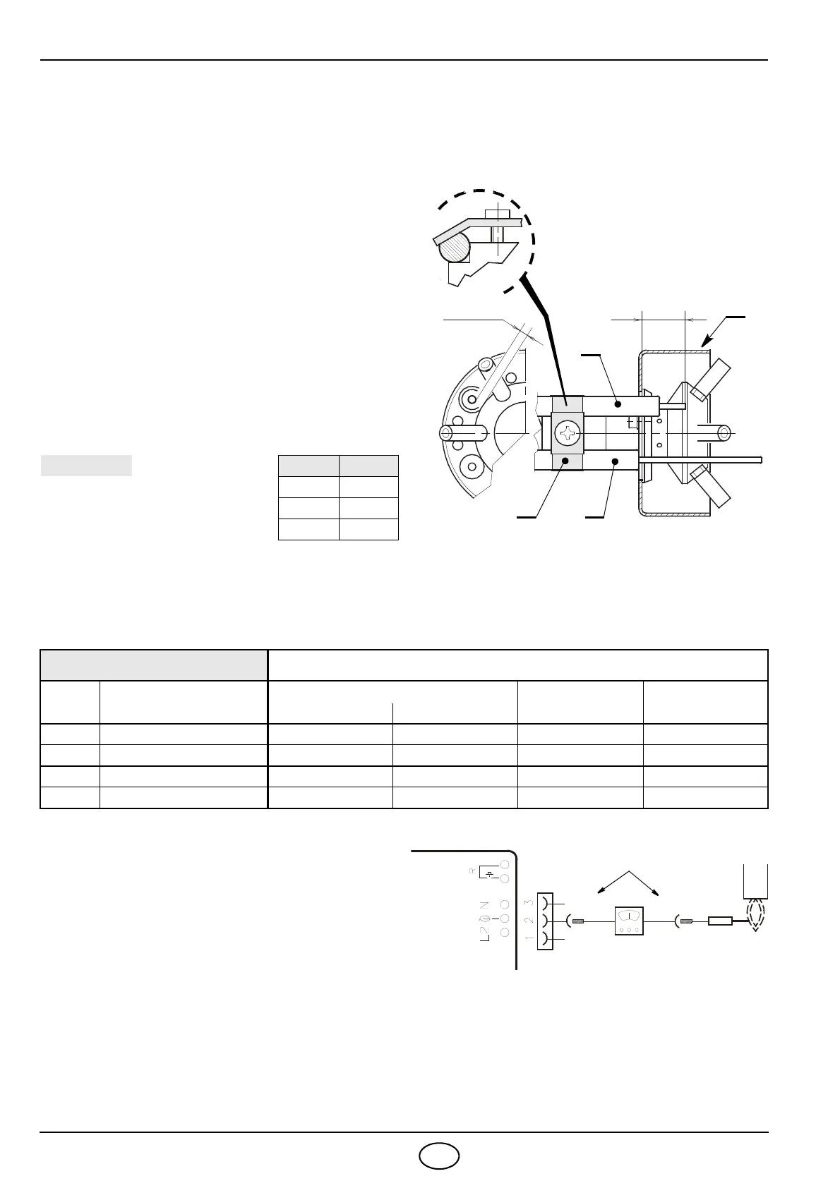
4.4 PROBE-ELECTRODE POSITIONING
Ensure that the plate (3, fig. 9) is always inserted in the
flattening of the electrode.
Lean the probe insulator (4) against the cup (2).
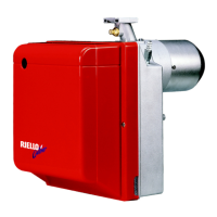
4.5 COMBUSTION CHECK
It is advisable to set the burner according to the type of gas used and following the indications of the table:
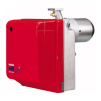
IONIZATION CURRENT
The minimum current necessary for the con-
trol box operation is 5 µA.
The burner normally supplies a higher cur-
rent value, so that no check is needed. Any-
way, if you want to measure the ionization
current, you have to open the connector
(CN1 see electrical scheme page 10) fitted
on the wire and insert a microammeter.
EN 676
AIR EXCESS: max. output λ ≤ 1.2 – min. output λ ≤ 1.3
GAS
Theoretical max. CO
2
0 % O
2
Setting CO
2
%
CO
mg/kWh
NO
x
mg/kWh
λ = 1.2 λ = 1.3
G 20 11.7 9.7 9.0
≤ 100 ≤ 170
G 25 11.5 9.5 8.8
≤ 100 ≤ 170
G 30 14.0 11.6 10.7
≤ 100 ≤ 230
G 31 13.7 11.4 10.5
≤ 100 ≤ 230
D6088
± 0.3
3.5 ± 0.3
A
Fig. 9
1
3
2
4
TYPE A (mm)
912 T2 30
913 T2 31
914 T2 31
KEEP TO GIVEN DISTANCES
ATTENTION