20098824
11
GB
4. WORKING
4.1 COMBUSTION ADJUSTMENT
The application of the burner to the heat generator, adjustment and testing must be carried out observing
the instruction manual of the boiler, including verification of the CO and CO
2
concentration in the flue gases,
their temperatures and the average temperature of the water in the generator.
To suit the required appliance output, choose the proper setting of the combustion head, and the air damper
opening.
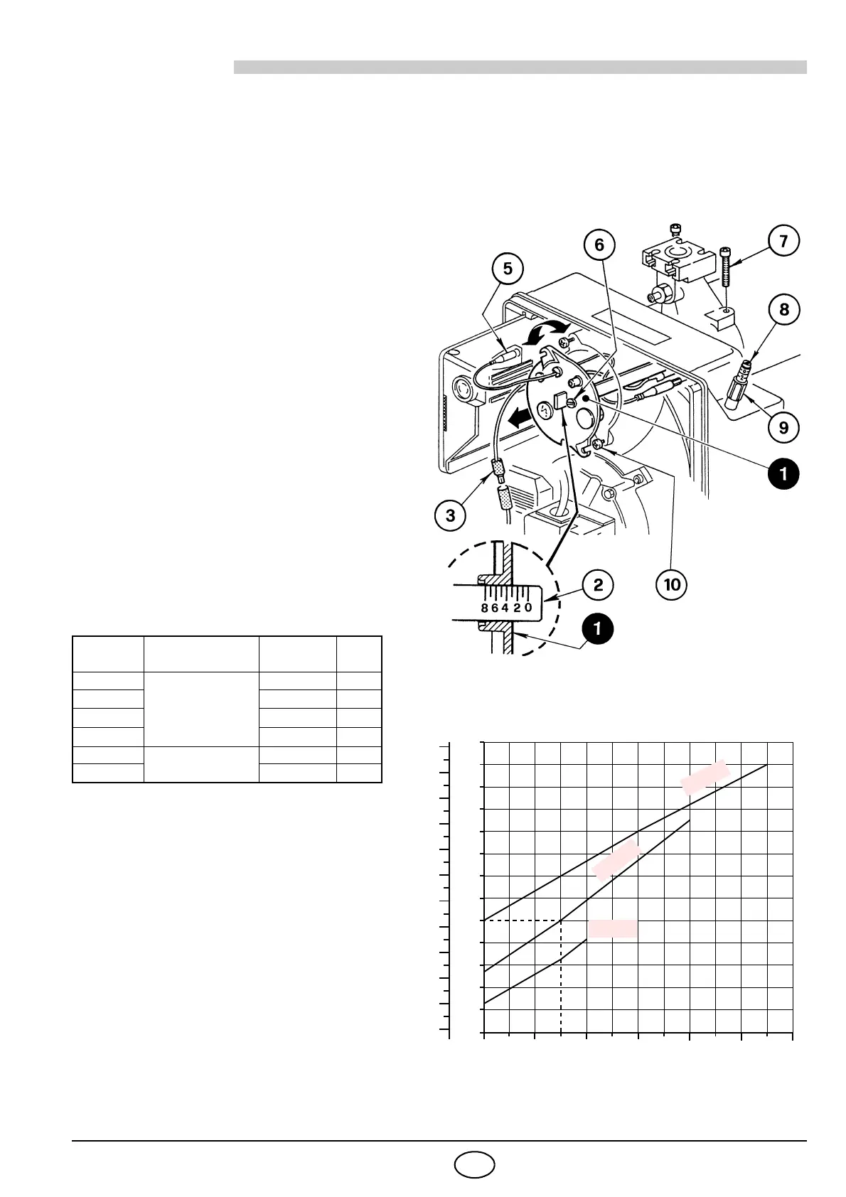
4.2 COMBUSTION HEAD SETTING,
(see fig. 8)
The combustion head is set in the factory
(see Tab.)
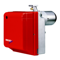
Setting depends on the output of the burner.
Rotate the setting screw (6) in a clockwise or
anticlockwise direction until set point marked
on the regulating rod (2) is level with the out-
side plane of the head assembly (1).
Figure 8 shows the head regulating rod set
on set point 3.
Example for burner type 913 T2:
The burner is installed in a 100 kW heat gen-
erator. Taking an efficiency level of 90% the
burner should give an output of app. 110 kW
with the regulating rod set at set point 3 as
shown in the diagram.
The diagram is for indication purposes: to as-
sure good working from the burner we sug-
gest adjusting the combustion head
according to the heat generator.
REMOVING THE HEAD ASSEMBLY
Proceed as follows to remove the head as-
sembly:
Disconnect the connections (3 and 5) and
loosen the screws (10).
Unscrew and remove the screws (7), pull
out the head assembly support (1) turning
it slightly to the right.
Take care not to change the setting posi-
tion on the elbow-bracket (2) during dis-
mantling.
REASSEMBLING THE HEAD ASSEMBLY
Follow the above instructions in reverse, re-
turning the head assembly (1) to its original
position.
CODE HEAD SETTING MODEL TYPE
20098812 1 BS2F 912T2
20098813 BS2F-GPL 912T2
20098814 BS3F 913T2
20098815 BS3F-GPL 913T2
20098817 2 BS4F 914T2
20098818 BS4F-GPL 914T2
10
30
50
70
90
110
130
150
170
190
210
230
250
270
kW
0
2
4
6 8
10
12
10.000
50.000
90.000
130.000
170.000
210.000
kcal/h