20148646
26
Installation
5.12.2 Gas train
Type-approved in accordance with EN 676 and supplied sepa-
rately from the burner.
To select the correct gas train model, refer to the manual "Burner-
gas train combination" supplied with the unit.
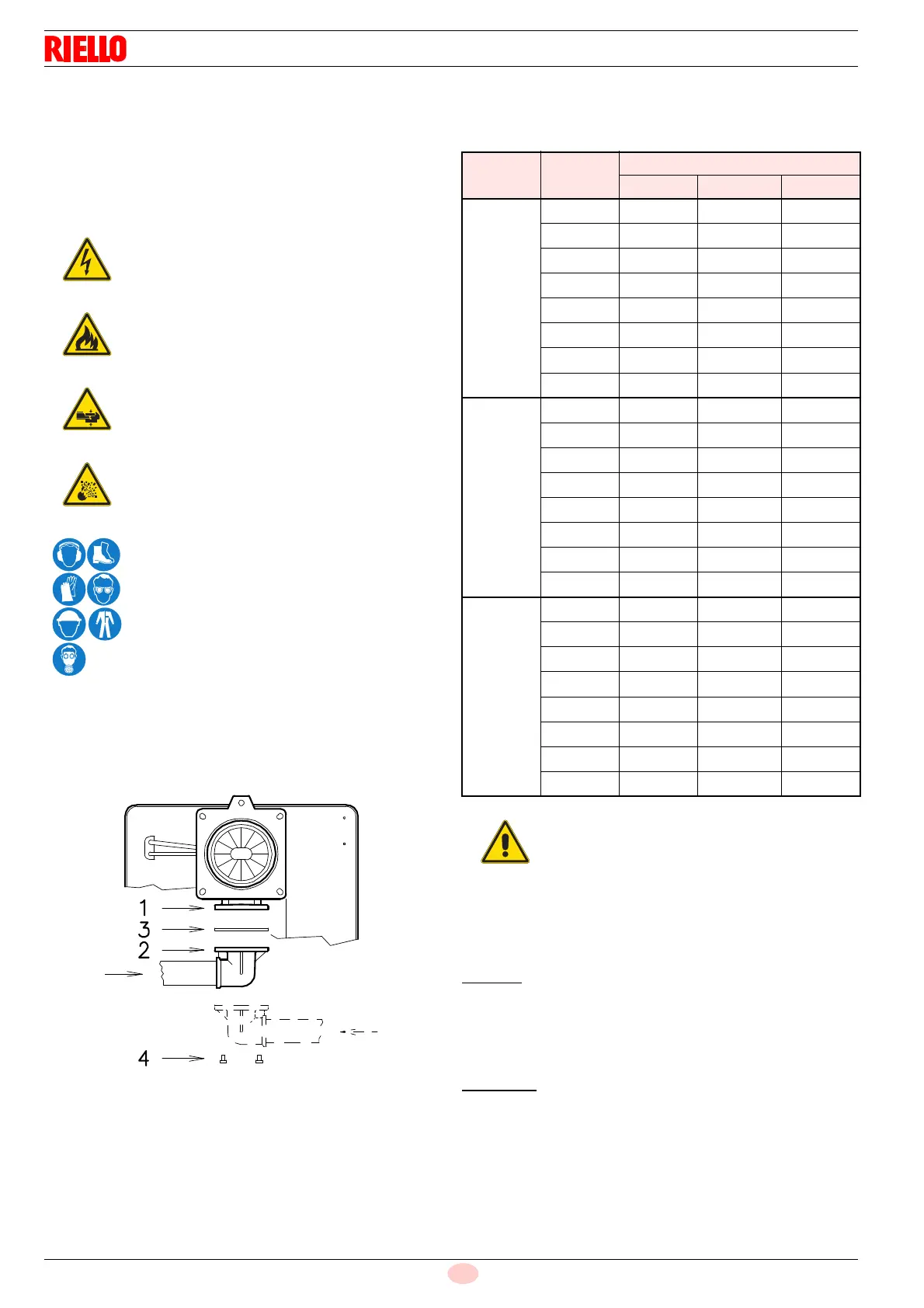
5.12.3 Gas train installation
The gas train must be connected to the gas connection 1)
(Fig. 28), using the flange 2), the gasket 3) and the screws 4)
supplied with the burner.
The train can enter the burner from the right or left side, depend-
ing on which is the most convenient, see Fig. 28.
5.12.4 Gas pressure
Tab. K indicates the pressure drops of the combustion head and
gas butterfly valve, on the basis of the burner operating output.
Tab. K
The values shown in Tab. K refer to:
– Natural gas G 20 NCV 9.45 kWh/Sm
3
(8.2 Mcal/Sm
3
)
– Natural gas G 31 NCV 27 kWh/Sm
3
(23.2 Mcal/Sm
3
)
Column 1
Combustion head pressure drop.
Gas pressure measured at test point 1)(Fig. 29), with:
– combustion chamber at 0 mbar;
– Burner operating in 2nd stage
– Gas G20 (methane) - G31 (propane)
To calculate
the approximate output at which the burner operates
in the 2nd stage:
– subtract the combustion chamber pressure from the gas
pressure measured at test point 1) (Fig. 29).
– Find in Tab. K related to the burner concerned, the pressure
value closest to the result of the subtraction.
– Read the corresponding output on the left.
Disconnect the electrical power using the main
switch.
Check that there are no gas leaks.
Pay attention when handling the train: danger of
crushing of limbs.
Make sure that the gas train is properly installed
by checking for any fuel leaks.
The operator must use the required equipment
during installation.
Model kW
1 p (mbar)
G20 G25 G31
RLS 28
163 6.5 9.7 5.5
185 6.8 10.1 5.7
210 7.3 10.9 6
235 8 11.9 6.3
260 8.7 13.0 6.7
285 9.6 14.3 7.4
310 10.4 15.5 8.5
325 11 16.4 9.5
RLS 38
232 8.8 13.1 9.7
260 9.1 13.6 10
290 9.4 14.0 10.3
320 9.8 14.6 10.6
350 10.4 15.5 10.9
380 11.1 16.5 11.2
410 11.8 17.6 11.5
442 13 19.4 12
RLS 50
290 10 14.9 8.8
330 10.2 15.2 8.9
370 10.5 15.6 9
410 10.8 16.1 9.1
450 11.3 16.8 9.2
490 11.7 17.4 9.3
530 12.7 18.9 9.7
581 14 20.9 10.5
Data of head thermal power and gas pressure
refer to operation with gas butterfly valve fully
open (90°).