20148646
28
Installation
5.13 Electrical connections
Notes on safety for the electrical wiring
Before carrying out any maintenance, cleaning or checking oper-
ations:
If the cover is still present, remove it and proceed with the electri-
cal wiring according to the wiring diagrams.
Use flexible cables in compliance with the EN 60 335-1 standard.
5.13.1 Supply cables and external connections
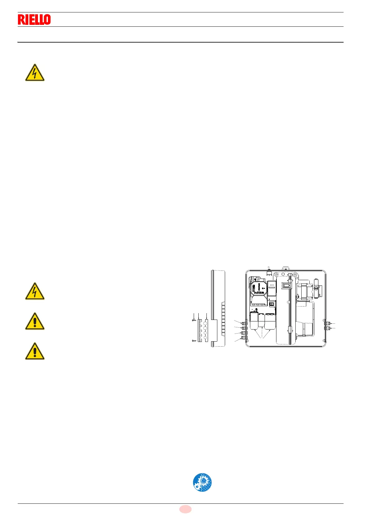
passage
All the cables to be connected to the burner plugs 7)(Fig. 30) are
passed through cable grommets to be inserted in the holes of the
plate, left or right, after having unscrewed the screws 8), opened
the plate at parts 9) and 10) and removed the thin diaphragm that
closes the holes.
The use of the cable grommets and the pre-blanked holes can be
done in different manners; for example (Fig. 30):
Key (Fig. 30)
RLS 28 and RLS 38
1 Pg 11 Single-phase power supply
2Pg 11 Gas valves
3 Pg 9 TL remote control
4 Pg 9 TR remote control
5 Pg 11 Gas pressure switch or gas valve leak
detection control device
RLS 50
1 Pg 11 Three-phase power supply
2 Pg 11 Single-phase power supply
3 Pg 9 TL remote control
4 Pg 9 TR remote control
5Pg 11 Gas valves
6 Pg 11 Gas pressure switch or valve leak
detection control device
The electrical wiring must be carried out with the electrical supply disconnected.
Electrical wiring must be made in accordance with the regulations currently in force in the country of destination
and by qualified personnel. Refer to the wiring diagrams.
The manufacturer declines all responsibility for modifications or connections different from those shown in the
wiring diagrams.
Check that the electrical supply of the burner corresponds to that shown on the identification label and in this
manual.
The burner has been set for intermittent operation (FS1).
The RFGO safety device features two built-in flame amplifiers which allow using it for applications with UV sensor
only, FR sensor only or with both sensors (UV+FR).
The FR amplifier circuit is subject to constant auto-control, which allows to use it for applications requiring a
burner operating cycle longer than 24 hours. When it is used as a UV control, the system is considered as non-
permanent, requiring one burner recycle every 24 hours.
Normally, burner stopping is guaranteed by the boiler's thermostat/pressure switch.
If this is not the case, a time switch must be applied to L-N in series, to stop the burner at least once every 24
hours. Refer to the wiring diagrams.
The electrical safety of the device is obtained only when it is correctly connected to an efficient earthing system,
made according to current standards. It is necessary to check this fundamental safety requirement.
In the event of doubt, have the electrical system checked by qualified personnel.
Do not use the gas tubes as an earthing system for electrical devices.
The electrical system must be suitable for the maximum power absorption of the device, as indicated on the label
and in the manual, checking in particular that the section of the cables is suitable for that level of power
absorption.
For the main power supply of the device from the electricity mains:
- do not use adapters, multiple sockets or extensions;
- make provisions for an omnipolar switch with a gap between the contacts of at least 3 mm (over-voltage
category III), as required by current safety regulations.
Do not touch the device with wet or damp body parts and/or in bare feet.
Do not pull the electric cables.
Disconnect the electrical supply from the burner
by means of the main system switch.
Close the fuel shut-off valve.
Avoid condensate, ice and water leaks from form-
ing.
After carrying out maintenance, cleaning or
checking operations, reassemble the cover and
all the safety and protection devices of the burner.