20148646
10
Technical description of the burner
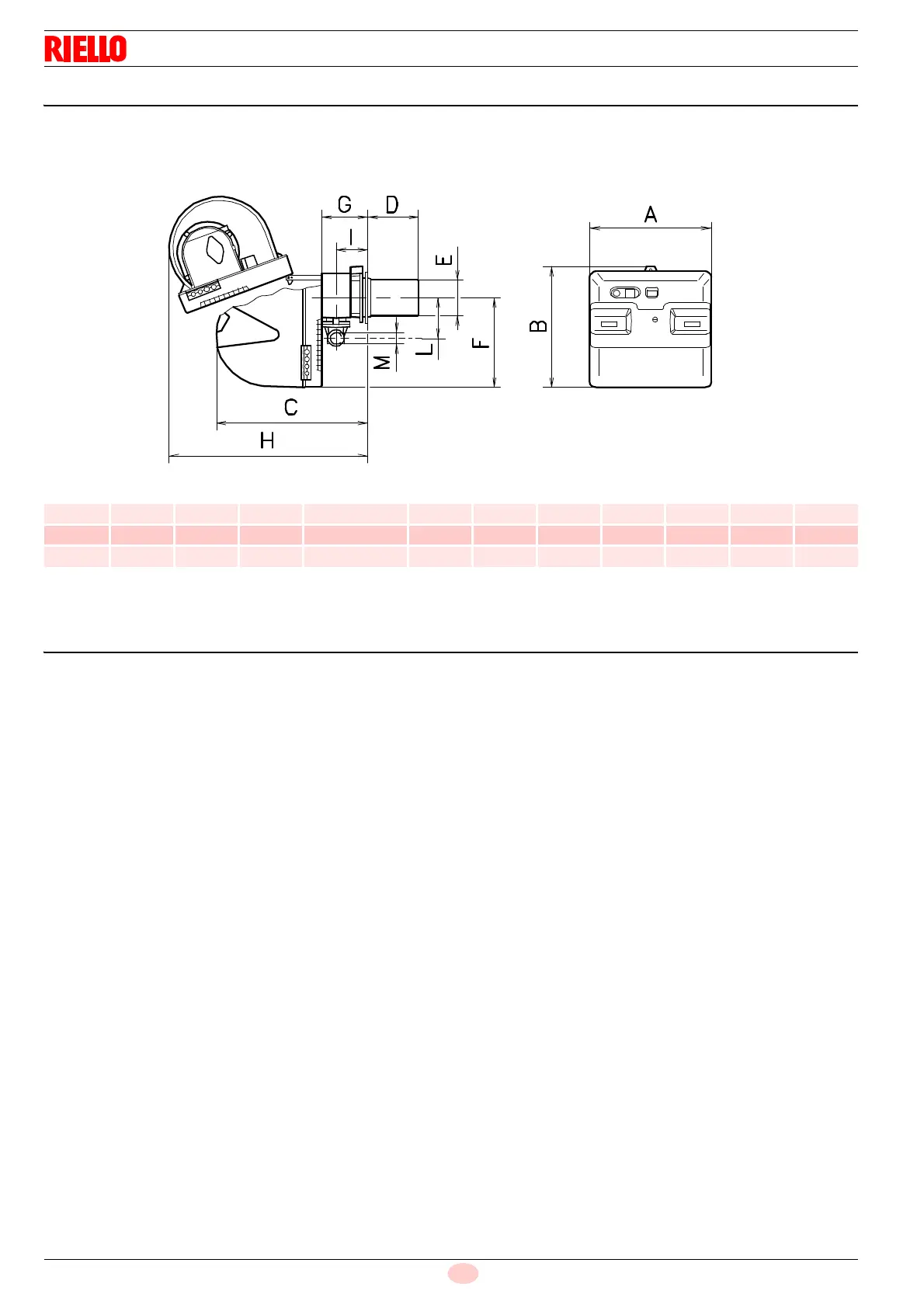
4.6 Maximum dimensions
The dimensions of the burner are given in Fig. 1.
Note that to inspect the combustion head the burner must be
moved backward and turned upward. The maximum dimension
of the burner, without casing, when open is given by measure-
ment H.
Tab. C
(1)
Blast tube: short-long
4.7 Burner equipment
Flange for gas train . . . . . . . . . . . . . . . . . . . . . . . . . . . . . . No. 1
Seal for flange . . . . . . . . . . . . . . . . . . . . . . . . . . . . . . . . . . No. 1
Flange fixing screws M 8 x 25 . . . . . . . . . . . . . . . . . . . . . . No. 4
Thermal flange gasket . . . . . . . . . . . . . . . . . . . . . . . . . . . . No. 1
Screws to fix the burner flange to the boiler: M 8 x 25 . . . . No. 4
Cable grommets for electrical wiring (RLS 28 and
RLS 38 single-phase) . . . . . . . . . . . . . . . . . . . . . . . . . No. 5
Cable grommets for electrical wiring
(RLS 50 three-phase). . . . . . . . . . . . . . . . . . . . . . . . . . . . . No. 5
Flexible hoses . . . . . . . . . . . . . . . . . . . . . . . . . . . . . . . . . . No. 2
Nipples for flexible hoses with gaskets . . . . . . . . . . . . . . . No. 2
Kit for LPG operation . . . . . . . . . . . . . . . . . . . . . . . . . . . . . No. 1
Label for LPG operation. . . . . . . . . . . . . . . . . . . . . . . . . . . No. 1
Instruction. . . . . . . . . . . . . . . . . . . . . . . . . . . . . . . . . . . . . . No. 1
Spare parts list . . . . . . . . . . . . . . . . . . . . . . . . . . . . . . . . . No. 1
mm A B C
D
(1)
EFGH I LM
RLS 28 476 474 580 191 - 326 140 352 164 810 108 168 1”1/2
RLS 38 476 474 580 201 - 336 152 352 164 810 108 168 1”1/2
RLS 50 476 474 580 216 - 351 152 352 164 810 108 168 1”1/2