20148646
18
Installation
5.4 Operating position
5.5 Preparing the boiler
5.5.1 Boring the boiler plate
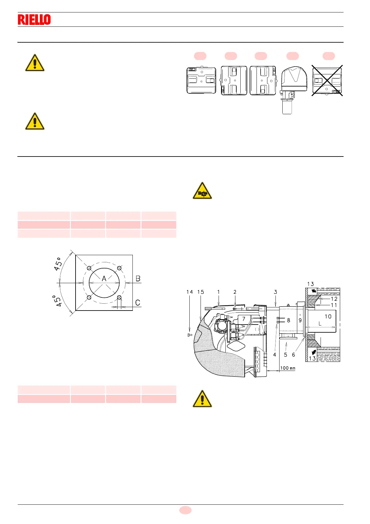
Pierce the closing plate of the combustion chamber, as in Fig. 10.
The position of the threaded holes can be marked using the ther-
mal insulation screen supplied with the burner.
Tab. F
5.5.2 Blast tube length
The length of the blast tube must be selected according to the in-
dications provided by the manufacturer of the boiler, and in any
case it must be greater than the thickness of the boiler door com-
plete with its fettling. The range of lengths available, L (mm), is as
follows:
Tab. G
For boilers with front flue passes 13) or flame inversion chamber,
a protection in refractory material 11) must be inserted between
the boiler fettling 12) and the blast tube 10).
This protection must not compromise the extraction of the blast
tube.
For boilers with a water-cooled front piece, a refractory lining 11)-
12)(Fig. 11) is not necessary, unless expressly requested by the
boiler manufacturer.
5.5.3 Securing the burner to the boiler
Separate the combustion head from the rest of the burner
(Fig. 11):
disconnect the light oil pipes unscrewing the two unions 4).
remove screw 14) and extract the cover 15).
remove screws 2) from the two slide bars 3).
remove screw 1) and pull the burner back on slide bars 3) by
about 100 mm.
Disconnect the wires of the electrodes and then pull the
burner completely off the slide bars, after removing the split
pin from the slide bar 3).
The burner is set up to operate only in posi-
tions 1, 2, 3 and 4 (Fig. 9).
Installation 1 is preferable, as it is the only
one that allows the maintenance operations
as described in this manual.
Installations 2, 3 and 4 permit operation but
make maintenance and inspection of the
combustion head more difficult.
Any other position could compromise the cor-
rect operation of the appliance.
Installation 5 are forbidden for safety rea-
sons.
mm A B C
RLS 28 160 224 M 8
RLS 38 160 224 M 8
RLS 50 160 224 M 8
mm RLS 28 RLS 38 RLS 50
Standard 191 201 216
Elongated 326 336 351
Provide an adequate lifting system.
The seal between burner and boiler must be
airtight.

 Loading...


