20148646
22
Installation
5.10 Light oil supply
The burner is equipped with a self-priming pump which is capable
of feeding itself within the limits listed in the table at the side.
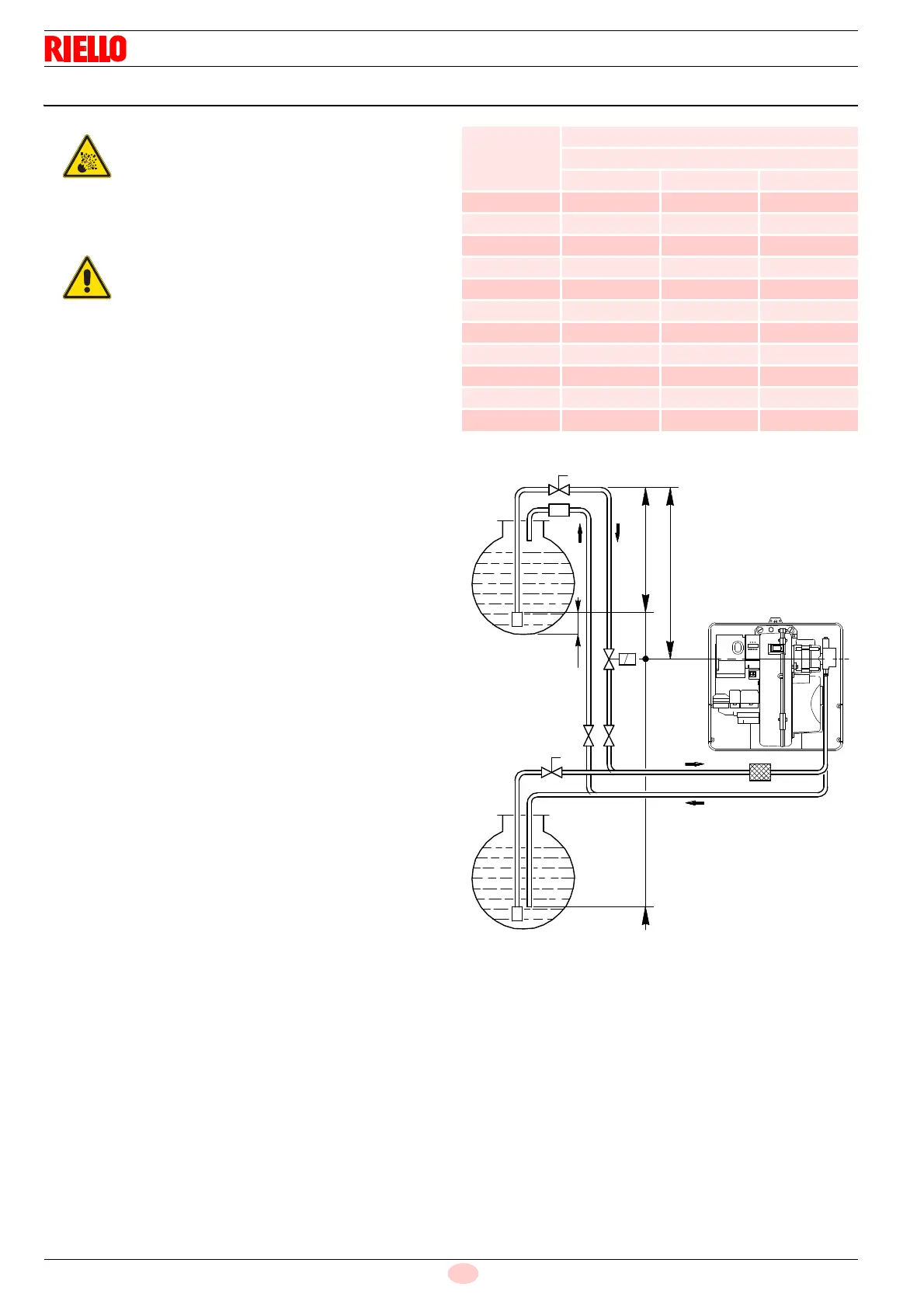
Tank higher than burner A (Fig. 20)
The distance "P" must not exceed 10 meters in order to avoid
subjecting the pump's seal to excessive strain; the distance "V"
must not exceed 4 meters in order to permit pump self-priming
even when the tank is almost completely empty.
Tank lower than burner B (Fig. 20)
Pump depression values higher than 0.45 bar (35°cm°Hg) must
not be exceeded. Because at higher levels gas is released from
the fuel; the pump becomes noisy and its lifetime is shortened.
It is good practice to ensure that the return and suction lines enter
the burner from the same height; the suction line is more difficult
to disconnect.
5.10.1 Loop circuit
The loop circuit is composed of a duct starting from the tank and
going back to it, in which an auxiliary pump makes the pressur-
ised fuel flow. A branch from the loop supplies the burner.
This circuit is extremely useful whenever the burner pump does
not succeed in self-priming because the tank distance and/or
height difference are higher than the values listed in Tab. I.
Tab. I
Key (Fig. 20)
H = Pump/Foot valve height difference
L = Piping length
Ø = Inside pipe diameter
1 = Burner
2=Pump
3=Filter
4 = Manual on/off valve
5 = Suction line
6 = Foot valve
7 = Quick closing manual valve with remote control (Italy only)
8 = On/off solenoid valve (Italy only)
9 = Return line
10 = Check valve (Italy only)
Explosion danger due to fuel leaks in the pres-
ence of a flammable source.
Precautions: avoid knocking, attrition, sparks and
heat.
Make sure the fuel shut-off valve is closed before
performing any operation on the burner.
The fuel supply line must be installed by qualified
personnel, in compliance with current standards
and laws.
+/- H
[m]
L [m]
Ø [mm]
8 10 12
4.0 35 90 152
3.0 30 80 152
2.0 26 69 152
1.0 21 59 130
0.5 19 53 119
0 17 48 108
-4.0 - 6 20
-3.0 4 16 42
-2.0 9 27 64
-1.0 13 37 86
-0.5 15 43 97
Fig. 20
1
2
3
9
5
6
6
7
7
9
5
4
8
A
B
+ H
- H V
P
10 cm
10
D1135
 Loading...


