20148646
32
Start-up, calibration and operation of the burner
6.7 Burner adjustment (gas)
The optimum adjustment of the burner requires an analysis of
flue gases at the boiler outlet.
Adjust in sequence:
1 Burner output in 2nd stage
2 Burner output in 1st stage
3 Output upon ignition
4 Air pressure switch
5 Gas minimum pressure switch
6.7.1 Output in 2nd stage
2nd stage output must be selected within the firing rate range in-
dicated in page 11.
Turn switch 2)(Fig. 33) to the 2nd stage position: the servomotor
will open the air damper on the value previously set for the light
oil and will control the opening of the 2nd stage VR2 gas valve.
Adjustment of gas delivery
Adjust the gas delivery to the air quantity.
– If delivery needs to be reduced, diminish the adjuster outlet
gas pressure; if it is already very low, slightly close the 2nd
stage VR2 valve.
– If delivery needs to be increased, increase the adjuster outlet
gas pressure.
6.7.2 Output in 1st stage
1st stage output must be selected within the firing rate range in-
dicated in page 11.
Turn switch 2)(Fig. 33) to the 1st stage position: the servomotor
will close the air damper on the value previously set for the light
oil and will control the opening of the 1st stage VR1 gas valve.
Adjustment of gas delivery
Adjust the gas delivery to the air quantity by operating the 1st
stage VR1 gas valve.
6.7.3 Ignition output (gas)
According to standard EN 676:
Burners with MAX output up to 120 kW
Ignition can occur at the maximum operation output level. Exam-
ple:
• max. operation output: 120 kW
• max. output upon ignition: 120 kW
Burners with MAX output above 120 kW
Ignition must occur at a lower output than the max. operation out-
put.
If ignition output does not exceed 120 kW, no calculations are re-
quired. If ignition output exceeds 120 kW, the regulatory standard
sets that the value be defined according to the control box safety
time "ts":
– for "ts" = 2s, ignition output must be equal to or lower than 1/
2 of max. operation output;
– for "ts" = 3s, ignition output must be equal to or less than 1/3
of max. operation output.
Example:
MAX operation output of 600 kW.
Ignition output must be equal to or lower than:
• 300 kW con ts = 2s
• 200 kW con ts = 3s
In order to measure the ignition output:
– Remove the UV sensor 14)(Fig. 4 on page 13) (the burner
starts and locks out after the safety time).
– Perform 10 ignitions with consecutive lockouts.
– Read the quantity of gas burned on the meter. This quantity
must be equal to or lower than the quantity given by the for-
mula:
Example for G 20 gas (10 kWh/Nm
3
):
Max operation output, 600 kW
corresponding to 60 Nm
3
/h.
After 10 ignitions with a lockout, the output indicated on the meter
must be equal to or less than:
60: 360 = 0.166 Nm
3
.
The ignition output must be adjusted on the gas valve brake.
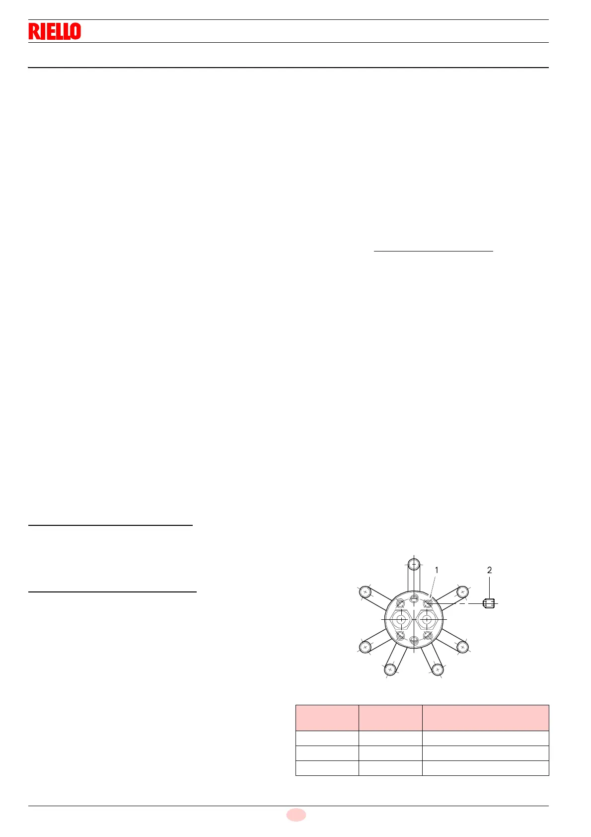
6.7.4 Operation with LPG - Propane - Butane
The RLS 28 - 38 - 50 burners can operate also with LPG -Pro-
pane-Butane.
In this case it is necessary to replace the six nozzles 2)(Fig. 37)
screwed onto the holes 1)(Fig. 37), which are suitable for natural
gas, with those for LPG-Propane-Butane, provided as standard
with the burner. See page 32.
Apply the adhesive label for LPG operation near the characteris-
tics label.
The firing rate and the adjustment of the burner are the same as
for natural gas.
The pressure of the G31 gas (Propane) is shown on page 26.
Gas train: use the train for natural gas, see page 26, with a 3/4”
or 1” diameter.
Nozzle hole
Tab. L
Burner
Natural gas
Ø mm
LPG/Propane/Butane
RLS 28 4 2.5
RLS 38 5 2.5
RLS 38 5 3
Nm
3
/h
(max. burner delivery)
360