20036644
10
Technical description of the burner
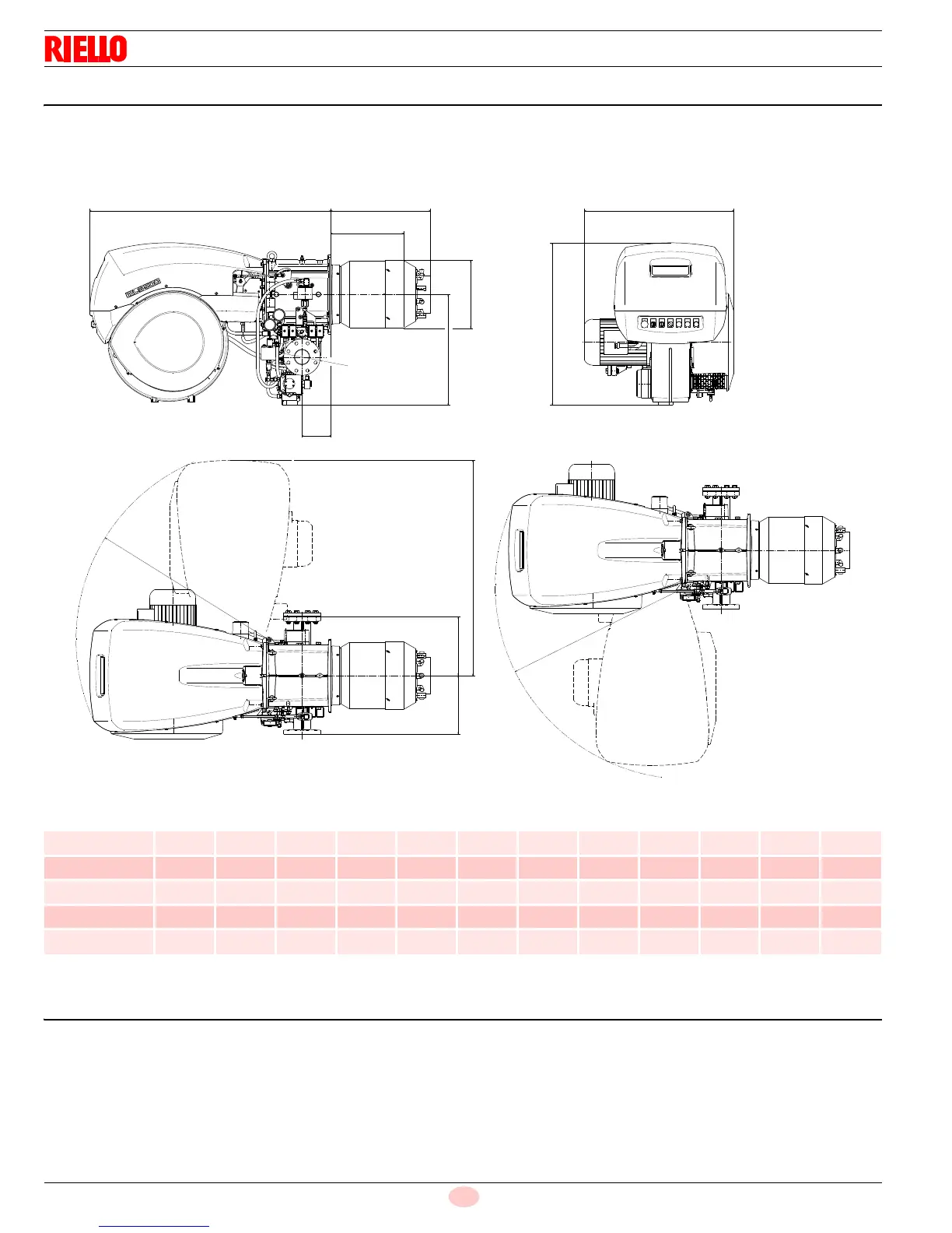
3.5 Burner dimensions
The maximum dimensions of the burner are given in Fig. 2.
Bear in mind that inspection of the combustion head requires the
burner to be opened by rotating the rear part on the hinge.
The overall dimensions of the burner when open are indicated by L
and R.
Tab. F
3.6 Standard equipment
Flange gasket. . . . . . . . . . . . . . . . . . . . . . . . . . . . . . . . . . . . . No. 1
Flange fixing screws (M16 x 50) . . . . . . . . . . . . . . . . . . . . . . No. 4
Screws (M18 x 60) to secure the burner flange to the boiler . No. 4
Spacers . . . . . . . . . . . . . . . . . . . . . . . . . . . . . . . . . . . . . . . . . No. 2
Instruction booklet . . . . . . . . . . . . . . . . . . . . . . . . . . . . . . . . . No. 1
inch ABCDEFGH I LRS
RLS 300/E 52
3
/
16“
20
1
/
2“
6
7
/
16“
12
5
/
16“
23
5
/
32“
ANSI 3” 31
5
/
32“
34
9
/
64“
14
1
/
32“
46
1
/
4“
41
17
/
32“
12
19
/
32“
RLS 400/E 52
3
/
16“
20
1
/
2“
6
7
/
16“
12
5
/
16“
23
5
/
32“
ANSI 3” 30
1
/
2“
34
9
/
64“
14
1
/
32“
46
1
/
4“
41
17
/
32“
12
19
/
32“
RLS 500/E 52
3
/
16“
20
1
/
2“
6
7
/
16“
14
17
/
32“
23
5
/
32“
ANSI 3” 30
1
/
2“
34
9
/
64“
14 46
1
/
4“
41
17
/
32“
12
19
/
32“
RLS 650/E 52
3
/
16“
22
29
/
32“
6
7
/
16“
16
9
/
64“
23
5
/
32“
ANSI 3” 34
21
/
32“
34
9
/
64“
14
3
/
16“
46
1
/
4“
41
17
/
32“
12
19
/
32“
RLS 800/E 52
3
/
16“
22
29
/
32“
6
7
/
16“
16
27
/
32“
23
5
/
32“
ANSI 3” 37 34
9
/
64“
16
15
/
32“
46
1
/
4“
41
17
/
32“
12
19
/
32“