20036644
44
Start-up, calibration and operation of the burner
5.8 Burner starting
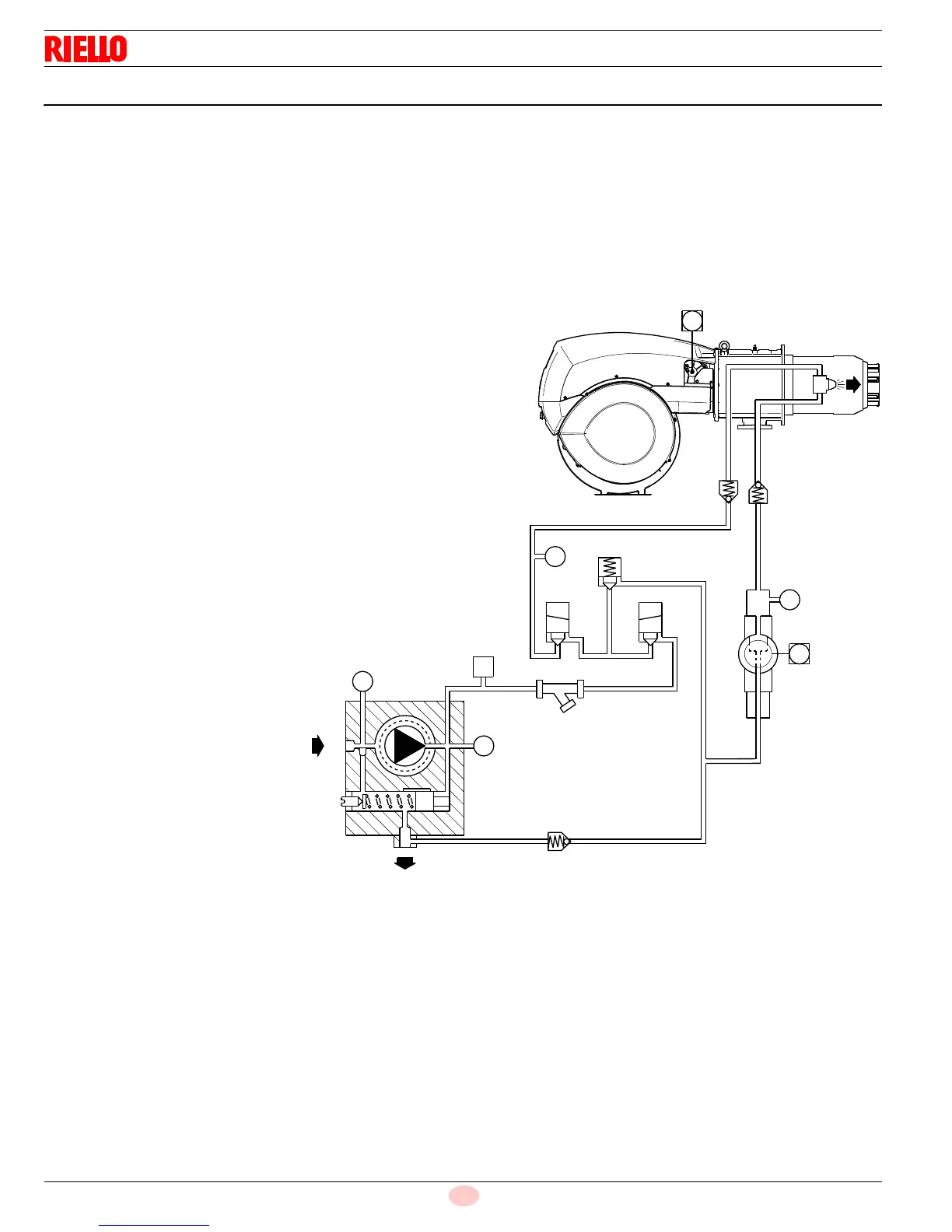
Operating control closes, the motor starts.
The pump 18)(Fig. 50) draws the fuel from the tank through
the piping 1) and pumps it under pressure for delivery.
The pump pressure governor 4) rises and the fuel returns to
the tank through the piping 2).
The screw 3) closes the by-pass heading towards suction and
the de-energized solenoid valves 5) - 6) close the passage to
the nozzle.
Air damper and pressure regulator are positioned on MIN out-
put.
The ignition pilot starts.
Solenoid valves 5) - 6) open; the fuel passes through the pip-
ing 19) and filter 12), and enters the nozzle.
A part of the fuel is then sprayed out through the nozzle, ignit-
ing when it comes into contact with the pilot flame: flame at a
low output level; the rest of the fuel passes through piping 20
at the pressure adjusted by the regulator 10), then, through
piping 2), it goes back into the tank.
The pilot flame goes out.
The starting cycle ends.
5.8.1 Steady state operation
At the end of the starting cycle, the servomotor control then passes
to load control for boiler pressure or temperature.
If the temperature or pressure is low (and the load control is
consequently closed), the burner progressively increases out-
put up to MAX.
If subsequently the temperature or pressure increases until
the load control opens, the burner progressively decreases
output down to MIN.
The burner shuts off when demand for heat is less than the
heat supplied by the burner in the MIN output.
The servomotor returns to the 0° angle. The air damper closes
completely to reduce thermal dispersion to a minimum.
Every time output is changed, the servomotor automatically modi-
fies oil delivery (pressure regulator) and air delivery (fan damper).
5.8.2 Firing failure
If the burner does not fire, it goes into lock-out within 5 sec. of
the opening of the light oil valve.
If the flame should go out for accidental reasons during opera-
tion, the burner will lock out in 1 s.
11
10
5
M
M
1
6
2
M
4
V
M
3
P
15
9
8
7
M
12
13
16
14
17
18
19
20
Key (Fig. 50)
1 Pump suction
2 Pump and nozzle return
3 By-pass screw in pump
4 Pump pressure governor
5 Safety valve
6 Safety valve
7 Nozzle delivery
8 Nozzle without interception pin
9 Nozzle return
10 Pressure variator on nozzle return
11 Servomotor for pressure variator
12 Check valve (no dripping function)
13 Check valve (no dripping function)
14 Check valve
15 Pressure switch on pump delivery
16 Strainer
17 Security relief valve
18 Pump
19 Piping
20 Piping
M Pressure gauge
V Vacuometer
D11478
Fig. 50