Installation
23
20036644
4.5 Removal of the locking screws from the shutter
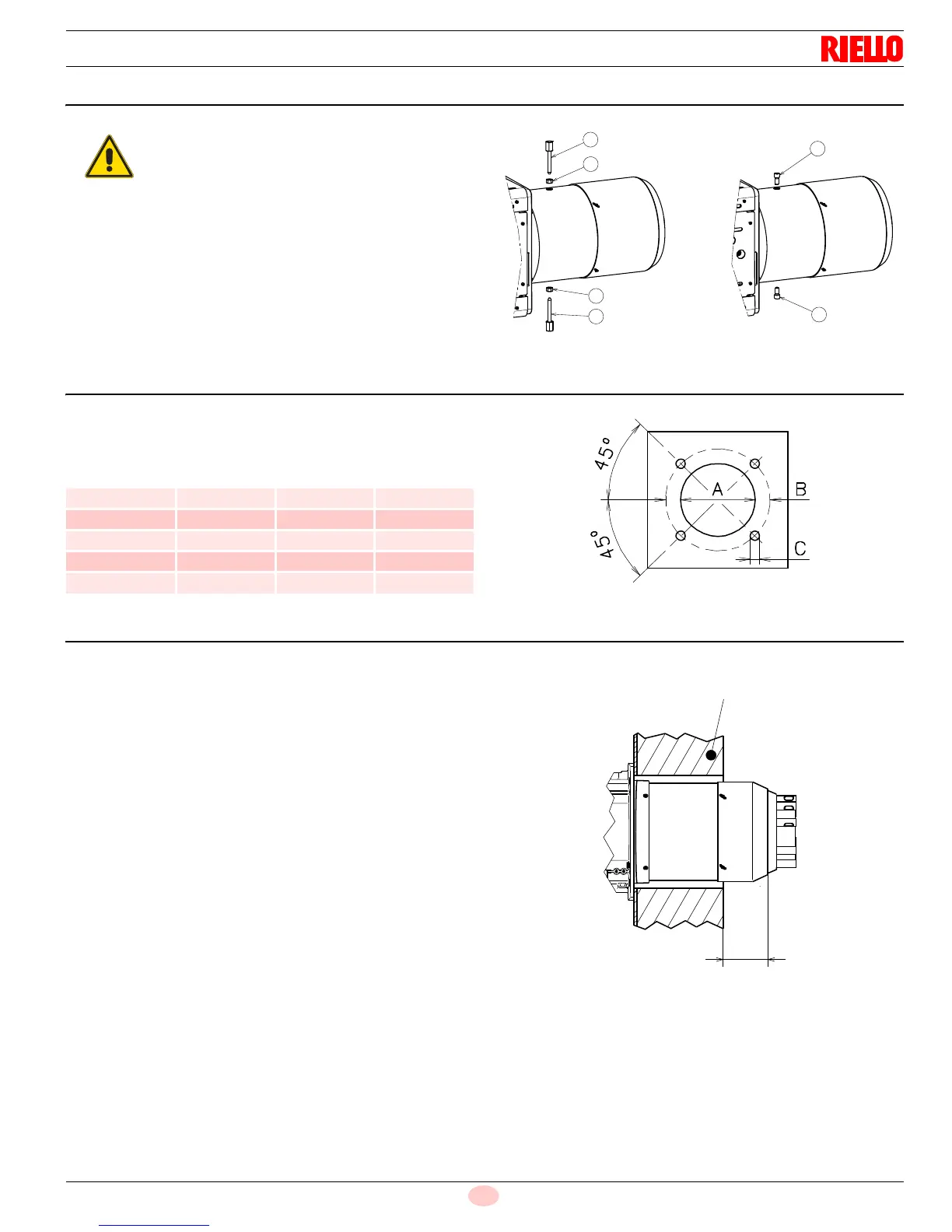
4.6 Boiler plate
Drill the combustion chamber mounting plate as shown in Fig. 12.
The position of the threaded holes can be marked using the gasket
supplied with the burner.
4.7 Securing the burner to the boiler
4.7.1 Blast tube length
The length of the blast tube must be selected according to the indi-
cations provided by the manufacturer of the boiler, and in any case
it must be greater than the thickness of the boiler door complete
with its fettling (the head should not jut out more than 4 ÷ 5 inch
Fig. 13).
4.7.2 Burner securing
Create a suitable hoisting system by hooking onto the rings 4),
removing the fastening screws 1) securing the cover 2) first.
Slip the thermal protection onto the blast tube 3).
Place entire burner on the boiler hole (arranged previously,
see Fig. 12), and fasten with the screws given as standard
equipment.
The coupling of the burner-boiler must be airtight.
Remove the screws and the nuts 1)-2)(Fig. 11),
before installing the burner on the boiler.
Replace them with the screws 3) M12 X 25 sup-
plied with the burner.
inch ABC
RLS 300/E 13
25
/
32”
17
51
/
64”
3
/
4”
coarse
RLS 400/E 13
25
/
32”
17
51
/
64”
3
/
4”
coarse
RLS 500/E 15
11
/
32”
17
51
/
64”
3
/
4”
coarse
RLS 650/E 17
5
/
16”
19
31
/
64”
3
/
4”
coarse
RLS 800/E 17
5
/
16”
19
31
/
64”
3
/
4”
coarse