Technical description of the burner
19
20036644
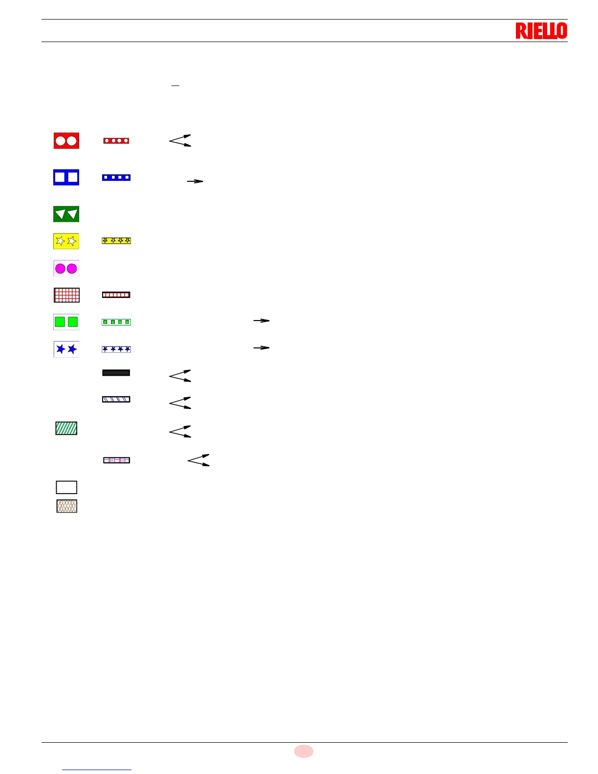
Key to the sequence diagrams:
Depending on the parameter, valve proving takes place:
between phase 62 and phase 70 or
/and
between phase 30 and phase 32.
Assignment of times:
t0 Postpurge lockout position
t01 Max. time safety phase
t10 Min. time home run
t21 Min. time start release
t22 Fan runup time t30 Prepurge time part 1
t34 Prepurge time part 3
t36 Min. ON time oil pump
t38 Preignition time gas / oil
t42 Preignition time OFF
t44 Interval 1 gas / oil
t62 Max. time low-fire
t70 Afterburn time
t74 Postpurge time 1 gas / oil (tn1)
t78 Postpurge time 3 gas / oil (tn3)
t80 Valve proving evacuate time
t81 Leakage test time atmospheric pressure
t82 Leakage test filling test
t83 Leakage test time gas pressure
tmn1 Min. time extraneous light test (5 s.) after skip over of
prepurge
tmx1 Max. damper running time
tmx2 Max. time startup release
tmx3 Max. time circulation heavy oil
tn Postpurge time
TSA1 Safety time 1
TSA2 Safety time 2
tv Prepurge time gas / oil
Signal ON Signal OFF Next phase
Parameter direct start
Checking with controller on
Deviation 10
No Rep. decrement
10
70
Without VP70 with VP80
62
Stop, up to Ph – max. time 01
Stop, up to Ph – max. time 10
Input: don´t care
Output: OFF
Output: ON