19
20068428
Technical description of the burner
4.12.1 List of phases
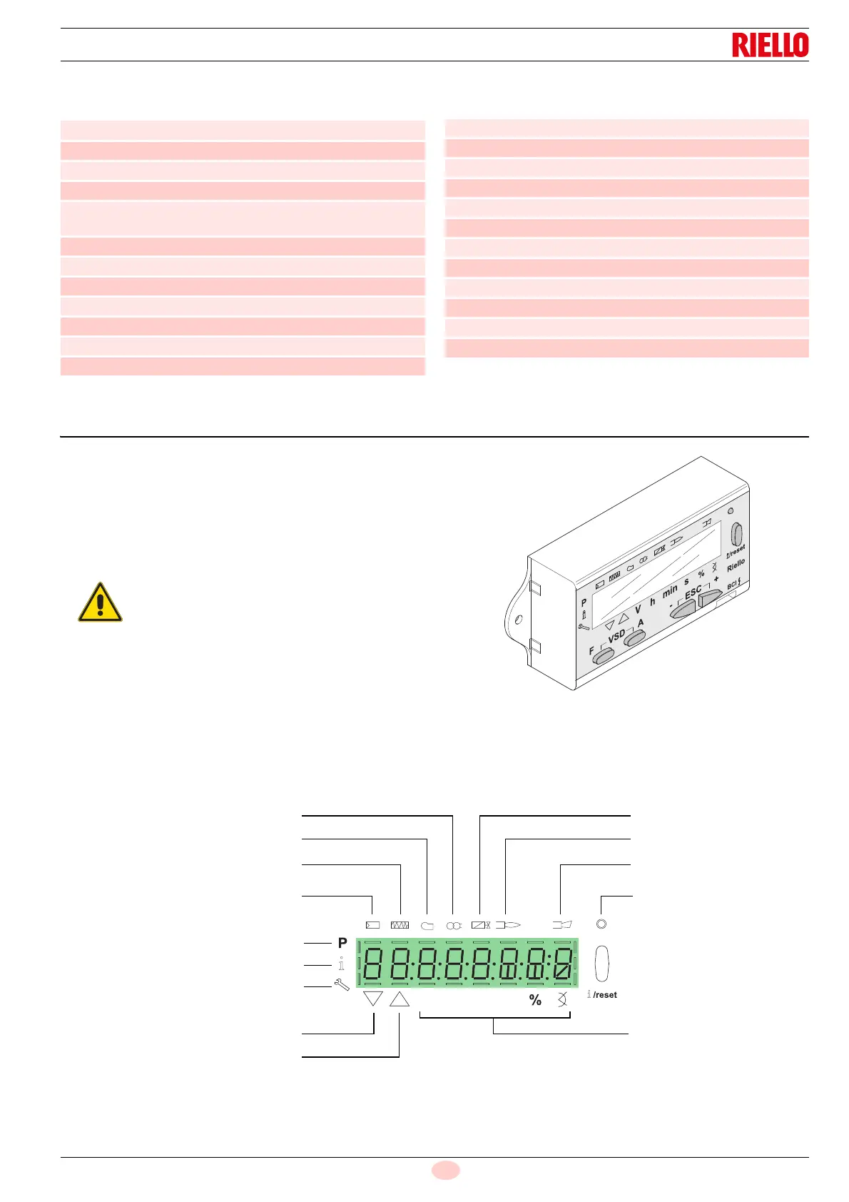
4.13 Operator panel operation
The control box REC 27.100A2 is directly connected to the oper-
ator panel (Fig. 8).
The buttons allow you to programme the operation and diagnos-
tics menus.
The burner management system is visualised on the LCD display
(Fig. 9). To simplify the diagnostics, the display shows the oper-
ating status, type of problem, and when the problem arose.
4.13.1 Symbols description on the display
The display brightness can be regulated from 0 ... 100% with pa-
rameter 126.
Phase Description
Ph00 Lockout phase
Ph02 Safety phase
Ph10 Closing paused
Ph12 Standby
Ph22 Fan motor (MV) = ON
Safety valve (VS) = ON
Ph24 The burner moves to the pre-purging position
Ph30 Pre-purging time
Ph36 The burner moves to the ignition position
Ph38 Ignition phase (TA) = ON
Ph39 Min. gas pressure switch test (PGmin.)
Ph40 Fuel valve (V) = ON
Ph42 Ignition (TA) = OFF
Ph44 t44 = interval time 1
Ph60 Operation
Ph62 The burner moves to the switching off position
Ph70 t13 = post-combustion time
Ph72 The burner moves to the post-purging position
Ph74 t8 = post-purging time
Ph78 t3 = post-purging time
Ph80 Emptying time (valve leak detection)
Ph81 Atmospheric test time (valve leak detection)
Ph82 Filling time (valve leak detection)
Ph83 Pressure test time (valve leak detection)
Ph90 Standby time due to lack of gas
Phase Description
Observe the procedures and adjustments
shown below.
All interventions (assembly and installation
operations, assistance, etc.) must be carried
out by qualified personnel.
If the display and operator panel are dirty,
clean them with a dry cloth.
Protect the panel from excessive tempera-
tures and liquids.
Lock-out lamp
Flame presence
Valve powered
Ignition transformer
Fan motor powered
Pre-heater active
Heat request
Info Mode active
Service Mode active
Closure of servomotors
Opening of servomotors
Measurement unit
Lockout
Parameters Mode active
only for light oil burners
V
h
min s