55
20068428
Maintenance
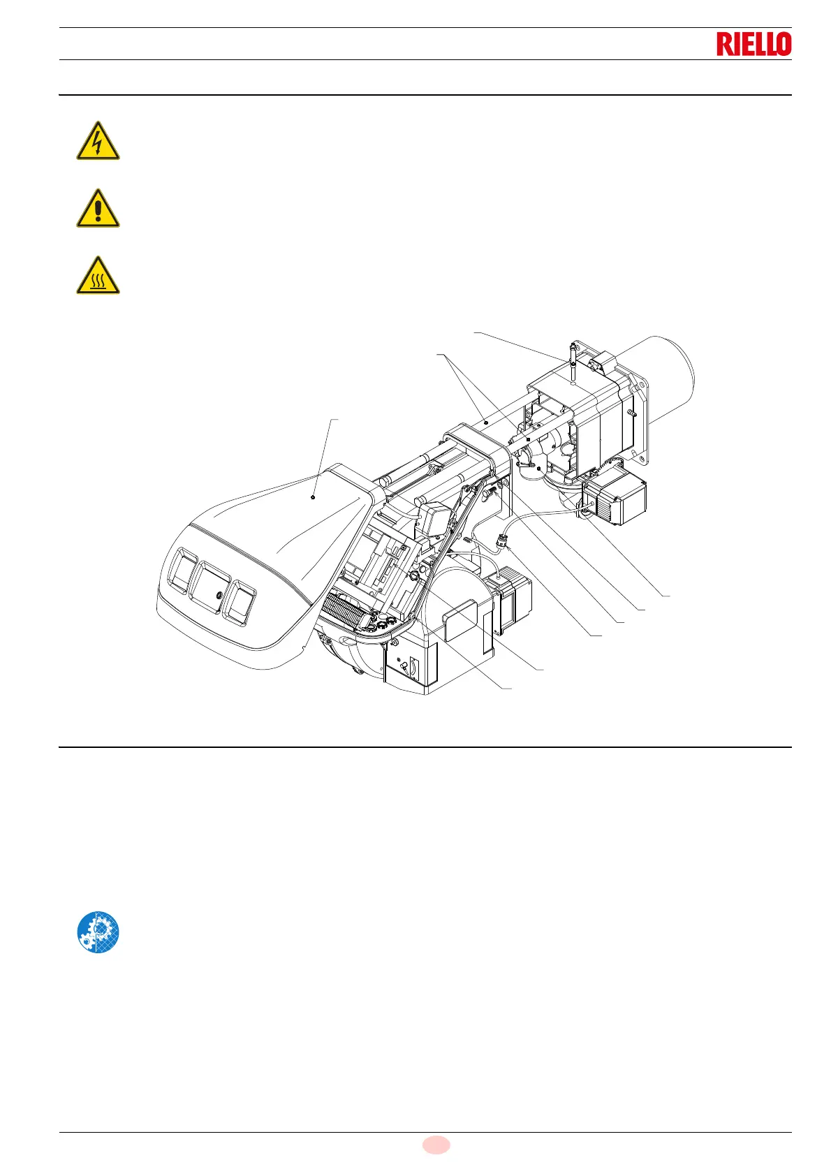
7.3 Opening the burner
Loosen the 4 screws 1)(Fig. 39) and remove the hood 2).
Assemble the two extensions supplied on the guides 4) (ver-
sions TL).
Disconnect the plug 7) and loosen the cable grommet 8);
Disconnect the socket from the maximum gas pressure
switch;
Remove the screws 3) and pull back the burner on the
guides 4) by about 100 mm.
Disconnect the cables of the probe and electrode, then pull
the burner back completely.
At this point it is possible to extract the inner part 5) after
having removed the screw 6).
7.4 Closing the burner
Push the burner up to approximately 100 mm from the pipe
coupling.
Reinsert the cables and slide the burner as far as the stop.
Connect the plug of the servomotor 7) and tighten the grom-
met 8).
Connect the socket of the maximum gas pressure switch.
Replace the screws 3) and carefully pull the probe and elec-
trode cables outwards until they are slightly taut.
Disassemble the two extensions from the guides 4).
Disconnect the electrical supply from the burner
by means of the main system switch.
Close the fuel interception tap.
Wait for the components in contact with heat
sources to cool down completely.
After carrying out maintenance, cleaning or
checking operations, reassemble the hood and all
the safety and protection devices of the burner.