2.4 Place of installation
R RTQ steel boilers must be installed in a dedicated boiler
room, with adequately sized vents, in compliance with applica-
ble laws and standards.
If at all possible, the boiler should be installed on a raised base
to prevent the burner fan sucking up dust.
9
When installing the boiler, allow sufcient space around it
to access all safety and control devices and to permit easy
maintenance.
9
If the specic weight of the gas supply to the burner is
greater than the specic weight of air, install all electrical
parts at least 500 mm above oor level.
0
Do not install the boiler outdoors. It is not designed to work
outdoors and is not tted with the necessary automatic an-
ti-frost systems to do so.
2.5 Installation in older systems and systems
requiring modernisation
When installing these boilers in old systems or systems requiring
modernisation, always perform the following checks:
− make sure that the stack is able to withstand the tempera-
ture of the combustion gases and that it has been designed
and mad
e in compliance with applicable standards. The
stack must also be as straight as possible, sealed, insulated
and not blocked or choked;
− make sure that the electrical system has been installed by a
qualied electrician in compliance with applicable stand
-
ards;
− make sure that the oil feed line and any oil storage tank are
made and installed in compliance with applicable stand-
ards;
− make sure that the expansion vessels are big enough to
contain the volume generated by thermal expansion;
− make sure that ow rate, head and direction of ow of the
pumps are suitable and correct;
− make sure that the circuit has been ushed out to remove
all sludge and lime scale, and has been vented and seal
tested.
− make sure that a suitable water treatment system is installed
if the quality of the supply/recirculation water so demands.
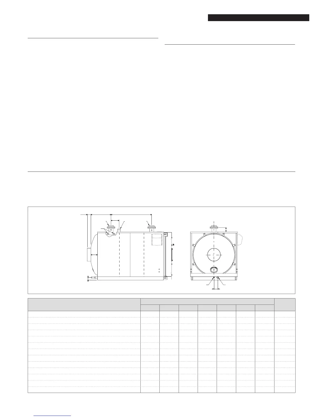
2.6 Water connections
R RTQ boilers are designed and made for use in central heating installations, but can also be used for domestic hot water pro-
duction if connected to a suitable storage cylinder. Water ttings are as specied in the following table.
9
Allow for the dimensions of the control panel that needs to be installed on top of the boiler.
G
DESCRIPTION
RTQ
953 1074 1308 1500 1700 2000 2336
1 Central heating ow * DN100 DN100 DN125 DN125 DN125 DN150 DN175 Ø
2 Instrument bulb / sensor socket G1/2" G1/2" G1/2" G1/2" G1/2" G1/2" G1/2" Ø
3 Safety device tting G1"1/2 G2"1/2 G2"1/2 DN 80 DN 80 DN100 DN100 Ø
4 Central heating return * DN100 DN100 DN125 DN125 DN125 DN150 DN175 Ø
5 Condensate drain G1" G1" G1" G1" G1" G1" G1" Ø
6 Boiler drain G1"1/4 G1"1/4 G1"1/4 G1"1/2 G1"1/2 G1"1/2 G1"1/2 Ø
A 1250 1300 1600 1650 1650 1650 1910 mm
B 505 580 655 700 700 735 745 mm
C 105 105 115 125 125 142 122 mm
D 300 250 650 380 380 280 510 mm
E 110 110 110 115 115 115 120 mm
F 95 95 115 120 120 117 155 mm
G 180 125 170 180 180 215 335 mm
(*) All anged connections are PN6 according to EN 1092-1.