2.8 Hoses should also be xed to the oor and
suitably protected whenever possible
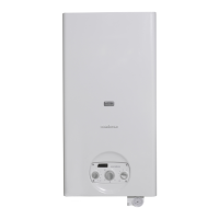
The ue gas exhaust and stack connection must be made in
compliance with applicable laws and standards, using heat re-
sistant, condensate resistant and stress resistant rigid pipe and
sealed joints.
H
0
30
6
0
9
0
Ø
RTQ
953 1074 1308 1500 1700
2000
2336
Ø (mm) 300 350 400 450 450 500 500
H (mm) 690 715 820 865 865 900 1000
9
The stack must guarantee the minimum draught specied
by applicable technical standards, assuming zero pressure
at the connection to the ue gas exhaust. Draught at the
stack must not exceed 0.2 mbar. Fit a draught limiter if
draught exceeds this value.
9
Inadequate or badly dimensioned stacks and exhausts can
increase combustion noise, cause condensation problems
and affect combustion parameters.
9
Uninsulated ues are potentially dangerous and can cause
burns.
9
Joints must be sealed using materials capable of withstand-
ing temperatures of at least 200°C (e.g. ller, mastic or sili-
cone based sealant).
9
The connection between the horizontal section of ue and
the vertical stack must be either straight or at an angle of no
more than 45°.
9
If more than one boiler is installed in the same utility room,
separate ues must be provided for each boiler. If this is not
possible, the burners should denitely be equipped with
automatic closing of the air damper.
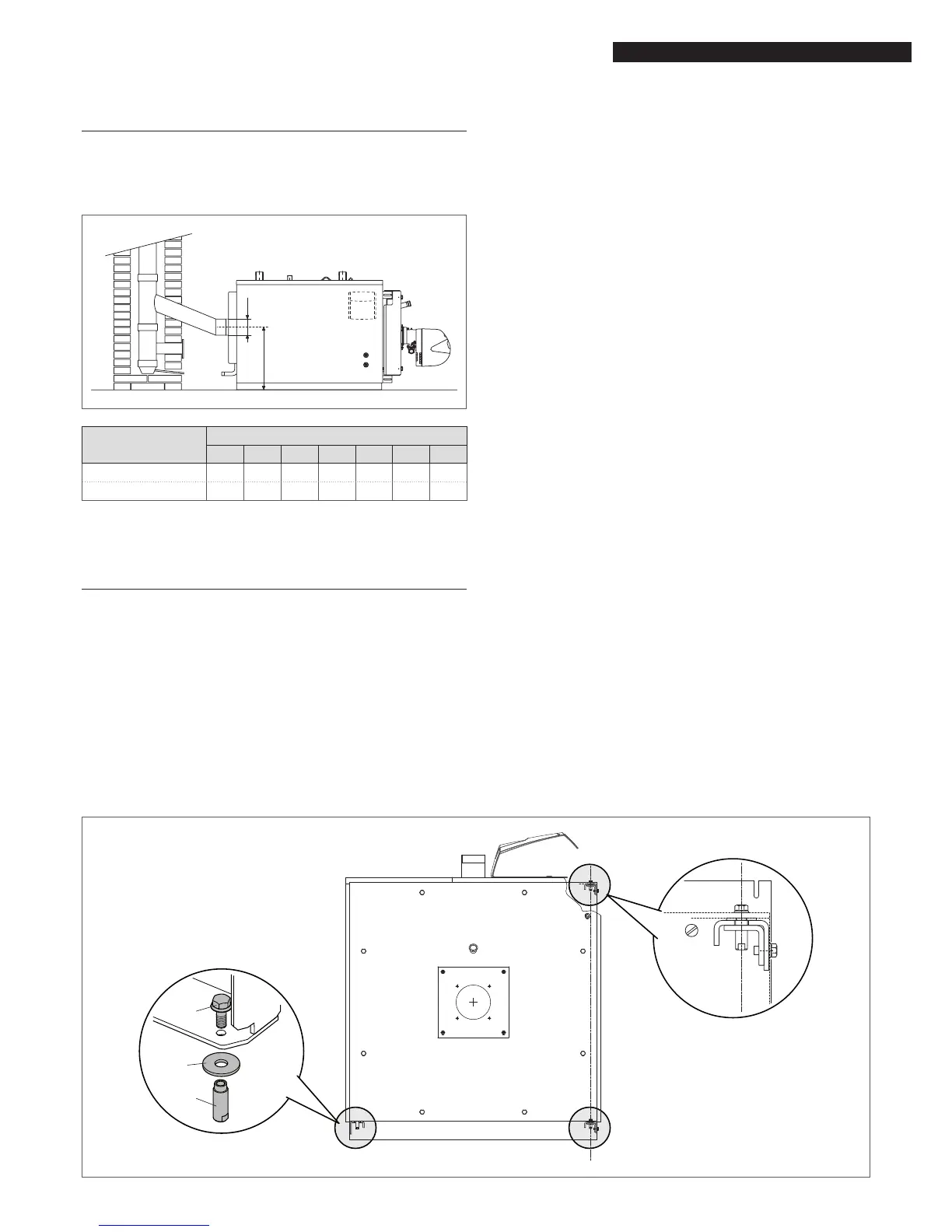
2.9 Door hinges
Boilers are tted with three door hinge points in the factory.
The doors are initially tted to open to the right. If you need to
change the door to open to the left, make the necessary modi-
cations before performing any tests that require the boiler door
to be opened. Proceed as instructed below to change the direc-
tion of door opening.
9
Once you have decided on the direction of door opening
and the door opens successfully, remove the unused hinge
assembly B.
Axis of door
rotation
A
A
B
1
2
3