RETURN
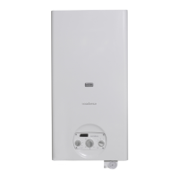
1 Boiler
2 Central heating system manifolds
3 Disconnect valves
4 System pumps
5 Non-return valves
6 Automatic vent valve
7 Boiler safety valve
8 Boiler drain cock
9 Storage cylinder safety valve
10 System lling cock
11 CH expansion vessel
12
R 7200 storage cylinder
13 Storage cylinder drain cock
14 DHW expansion vessel
15 Water softener lter
16 Pressure reducer
17 Anti-condensate pump
EAF Domestic cold water inlet
9
The choice of system components and the method of their
installation are left up to the heating engineer installing the
system. Installers must use their expertise to ensure proper
installation and functioning in conformity to all applicable
legislation.
9
Circuits lled with anti-freeze must be tted with water dis-
connectors.
9
If needed, water supplies and recovery circuits must be
conditioned by suitable treatment systems. See the table
alongside for reference values.
REFERENCE VALUES
pH 6-8
Electrical conductivity less than 200 μS/cm (25°C)
Chlorine ions less than 50 ppm
Sulphuric acid ions less than 50 ppm
Total iron less than 0.3 ppm
Alkalinity M less than 50 ppm
Total hardness less than 35°F
Sulphur ions none
Ammonia ions none
Silicon ions less than 30 ppm
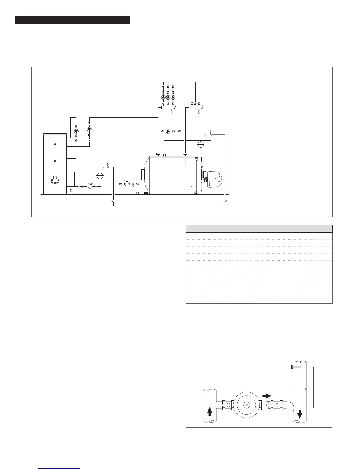
2.7 Anti-condensate pump
An anti-condensate pump operates during periods of no heat
request to avoid damage until the boiler returns to a stable op-
erating temperature. While the system is operating, this pump
must guarantee a ow rate between 20 and 30% maximum
ow to ensure a water return temperature no lower than 55 °C.
Pump shutdown must also be delayed for at least 3 minutes at
the beginning of extended periods of boiler shutdown (over-
night or weekend shutdown etc.).
9
A sensor socket must be positioned at a distance of 3 to 5
times the diameter of the water return pipe, upstream from
the water tting, to measure effective water return temper-
ature and control the anti-condensate pump or the tem-
perature controller stabilisation function.
9
Any temperature controllers installed remotely from the
control panel must be compatible with the system’s electri-
cal connections and functioning logic.
D
3÷5 D