3.8. Time domain reflectometer (TDR) mode
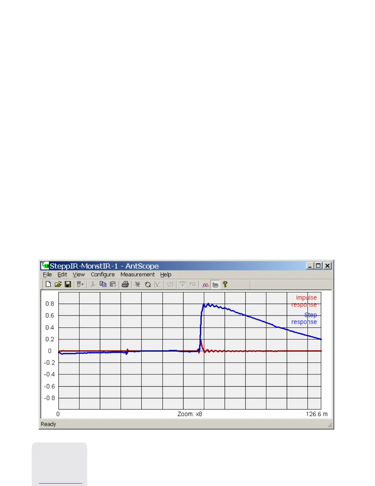
This mode (press F7) displays impulse response and step response graphs which
show how electromagnetic wave reflects from discontinuities in a cable. Additionally,
a tool tip near the cursor shows estimated value of the impedance of a cable at the
corresponding distance. This will let you know if your cable is in a good or a bad
condition.
For best results, perform a scan over the full frequency range with 1000 or more
points. Make sure the characteristic impedance and the velocity factor of the cable are
set in the Configure – Cable parameters menu. This will let you see the exact distance
to the discontinuity. For TDR measurements, it is not important if the cable ends with
antenna, open circuit or short circuit.
The following screen shot was taken in the real measurement. It shows 33 meters of 50
Ohm coaxial cable, antenna switching relay, and additional 35 meters of cable ending
with an HF antenna.
14