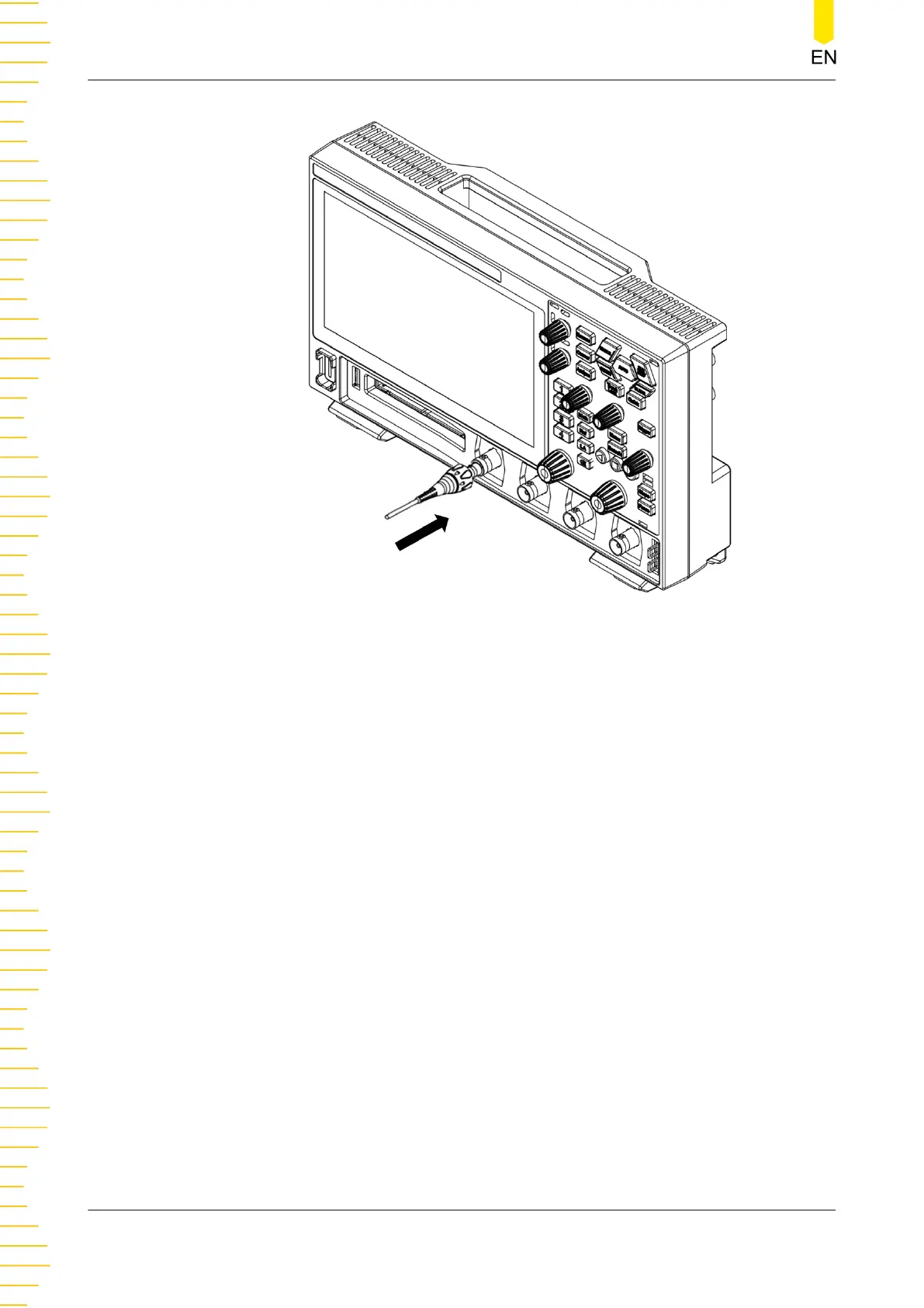
Figure 5.3 Connecting the Passive Probe
After you connect the passive probe, check the probe function and probe
compensation adjustment before making measurements. For details, please refer to
Function Inspection
and
Probe Compensation
.
Connect the Logic Probe
1. Connect the output terminal of the logic probe to the digital channel input
terminal on the front panel of the oscilloscope in the correct direction, as shown in
the figure below.
2. Connect the other terminal of the logic probe to the signal terminal under test.
DHO900 provides the optional PLA2216 active logic probe. To cater to different
application scenarios, PLA2216 provides two methods to connect the signal under
test. For details, refer to
PLA2216 Active Logic Probe User Guide
.
To Prepare for Use
16
Copyright ©RIGOL TECHNOLOGIES CO., LTD. All rights reserved.
 Loading...