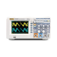
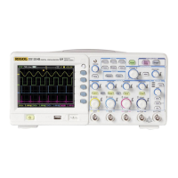
Note: When horizontal control is set under 50 ms/div, Auto mode allows the
oscilloscope not to capture trigger signal.
Normal:
The Normal mode allows the oscilloscope to acquire a waveform only when it is
triggered. If no trigger occurs, the oscilloscope keeps waiting, and the previous
waveform, if any, will remain on the display.
Single:
In Single mode, after pressing the RUN/STOP key, the oscilloscope waits for
trigger. While the trigger occurs, the oscilloscope acquires one waveform then
stop.
3. Coupling:
Trigger coupling determines which signal component passing to the trigger circuit.
Coupling types include AC, DC, LF Reject and HF Reject.
AC: AC coupling blocks DC components.
DC: DC coupling passes both AC and DC components.
LF Reject: LF Reject coupling blocks DC component, and attenuates all
signal with a frequency lower than 8 kHz.
HF Reject: HF Reject coupling attenuates all signals with a frequency higher
than 150 kHz.
4. Pre-trigger/delayed trigger:
The data collected before and after trigger.
The trigger position is typically set at the horizontal center of the screen. In the
full-screen display the 6div data of pre-trigger and delayed trigger can be surveyed.
More data (14div) of pre-trigger and 1s delayed trigger can be surveyed by
adjusting the horizontal knob.
This feature is very useful to study the events that led up to the trigger point.
Everything to the right of the trigger point is called post-trigger information. The
delay range (pre-trigger and post-trigger information) depends on the sweep
speed selected.
5. Adjustable trigger sensitivity
To avoid the influence of noise from the physical world, and get the stable trigger,
the trigger circuit has adopted Stickiness. In DS1000CA series, the stickiness is
adjustable from 0.1div-1.0div, which means when it sets to 1.0div, the trigger
circuit will not affect any signal with peak-peak amplitude less than 1.0div, so as to
avoid the influence of the noise.
 Loading...
