RIGOL
© 2006 RIGOL Technologies, Inc.
User‟s Guide for DS1000 Series
To Compensate Probes
Perform this adjustment to match the characteristics of the probe and the channel
input. This should be performed whenever attaching a probe to any input channel the
first time.
1. From CH1 menu, set the Probe attenuation to 10X (press CH1→Probe→10X). Set
the switch to 10X on the probe and connect it to CH1 of the oscilloscope. When
using the probe hook-tip, inserting the tip onto the probe firmly to ensure a
proper connection.
Attach the probe tip to the Probe compensator connector and the reference lead
to the ground pin, Select CH1, and then press AUTO.
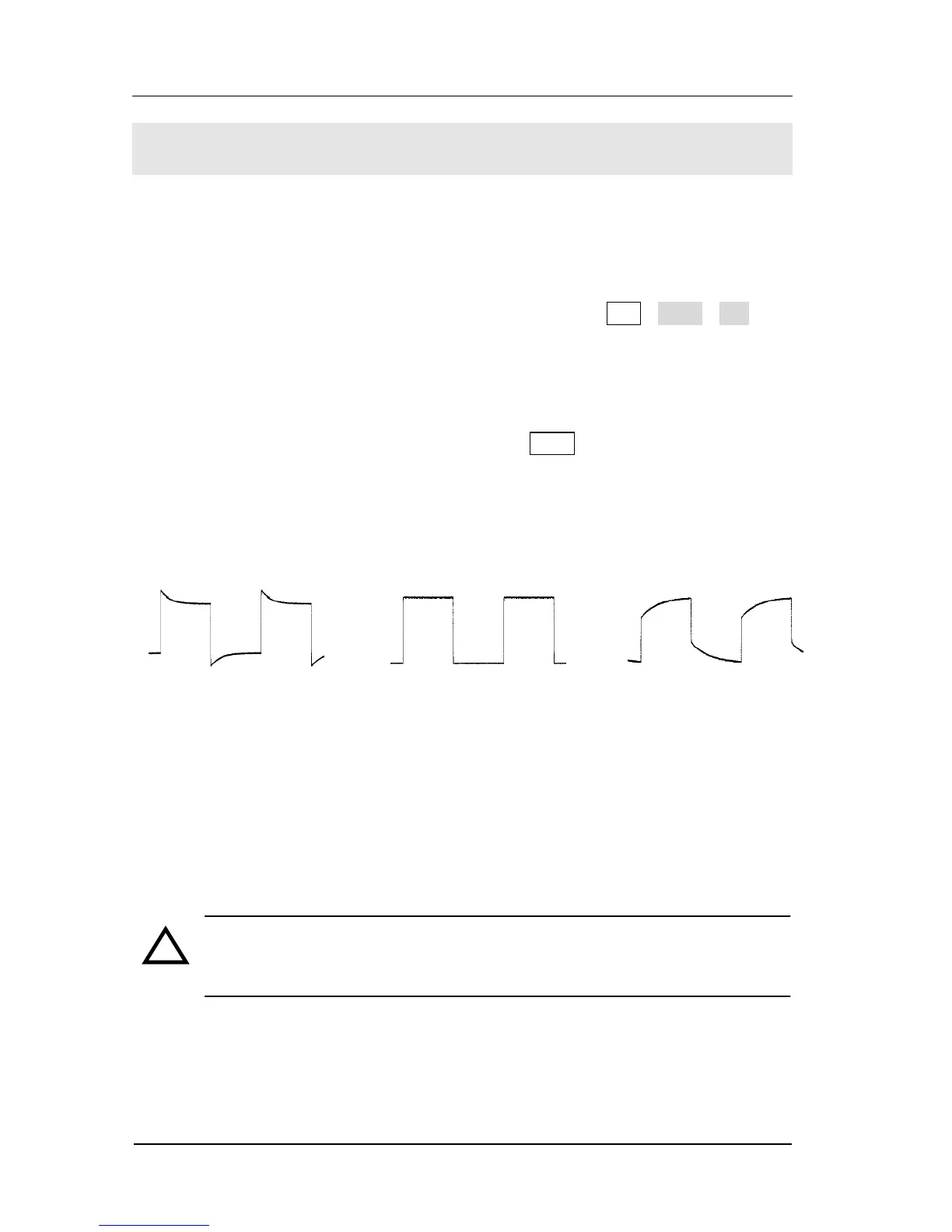
2. Check the shape of the displayed waveform.
Over compensated Correctly Compensated Under Compensated
Figure 1-9
Figure 1-9
Compensating Probe
3. If necessary, use a non-metallic tool to adjust the trimmer capacitor on the probe
for the flattest square wave possible as displayed on the oscilloscope.
4. Repeat as necessary.
WARNNING: To avoid electric shock while using the probe, be sure the
perfection of the insulated cable, and do not touch the metallic portions of
the probe head while it is connected with a voltage source.
 Loading...