RIGOL Chapter 7 Protocol Decoding
7-2 DS1000Z-E User Guide
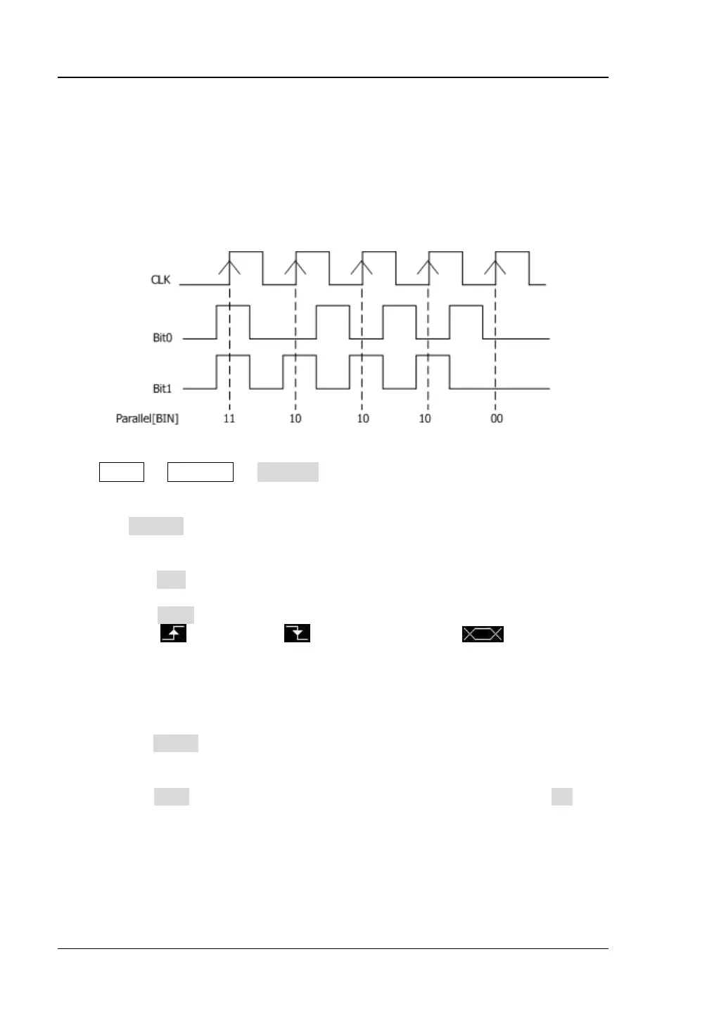
Parallel Decoding
Parallel bus consists of clock line and data line. As shown in the figure below, CLK is
the clock line, while Bit0 and Bit1 are the 0 bit and 1st bit on the data line respectively.
The oscilloscope will sample the channel data on the rising edge, falling edge or the
rising/falling edge of the clock and judge each data point (logic "1" or logic "0")
according to the preset threshold level.
Figure 7-1 Parallel Decoding
Press MATH Decode1 Decoder to select "Parallel" and open the parallel
decoding function menu.
1. Press Decode to turn on or off the decoding function.
2. Clock Line Setting (CLK)
Press CLK to select one of the channels (CH1 and CH2) as the clock channel.
If "OFF" is selected, no clock channel is set.
Press Edge to set the oscilloscope to sample the channel data on the rising
edge ( ), falling edge ( ) or rising/falling edge ( ) of the clock. If
no clock channel is selected, the instrument will sample when the channel
data jumps during the decoding.
3. Data Line Setting
Set the bus width
Press Width to set the data width of the parallel bus namely the number of
bits per frame. The default is 8 and the range is from 1 to 16.
Specify data channel for each bit.
Press Bit X to select the bit that needs to specify a channel. Press CH to
specify a channel source from CH1 or CH2.
4. Analog Channel Threshold Setting
To judge logic "1" and logic "0" of the buses, you need to set a threshold for
each analog channel (CH1 or CH2). When the signal amplitude is greater than
the preset value, it is considered as "1"; otherwise "0".