Front
Panel
Overview
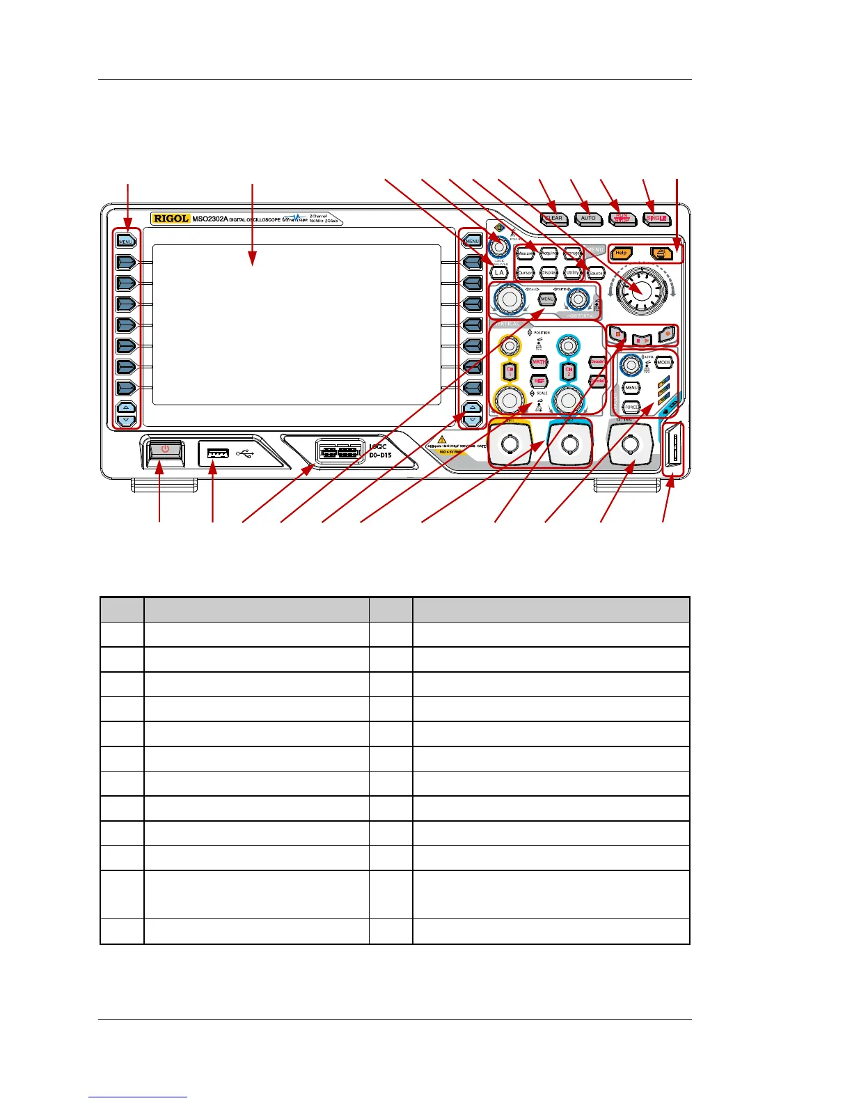
Figure 10 Front Panel Overview
Table 1 Front Panel Description
No. Description No. Description
1 Measurement Menu Softkeys 13 Power Key
2 LCD 14 USB HOST Interface
3 Logic Analysis Control Key
[1]
15 Digital Channel Input Interface
[1]
4 Multifunction Knob 16 HORIZONTAL Control Area
5 Function Menu Keys 17 Function Menu Softkeys
6 Signal Source
[2]
18 VERTICAL Control Area
7 Navigation Knob 19 Analog Channel Input Area
8 CLEAR 20 Waveform Record/Playback Control Keys
9 AUTO 21 TRIGGER Control Area
10 RUN/STOP 22 EXT TRIG Input Terminal
11 SINGLE 23
Probe Compensation Signal Output
Terminal/ Ground Terminal
12 Help/Print -- --
Note
[1]
: Only applicable to MSO2000A and MSO2000A-S models oscilloscopes.
Note
[2]
: Only applicable to MSO2000A-S and DS2000A-S models oscilloscopes.
3 4 5 6 7 8 9 10 11 12 1 2
 Loading...