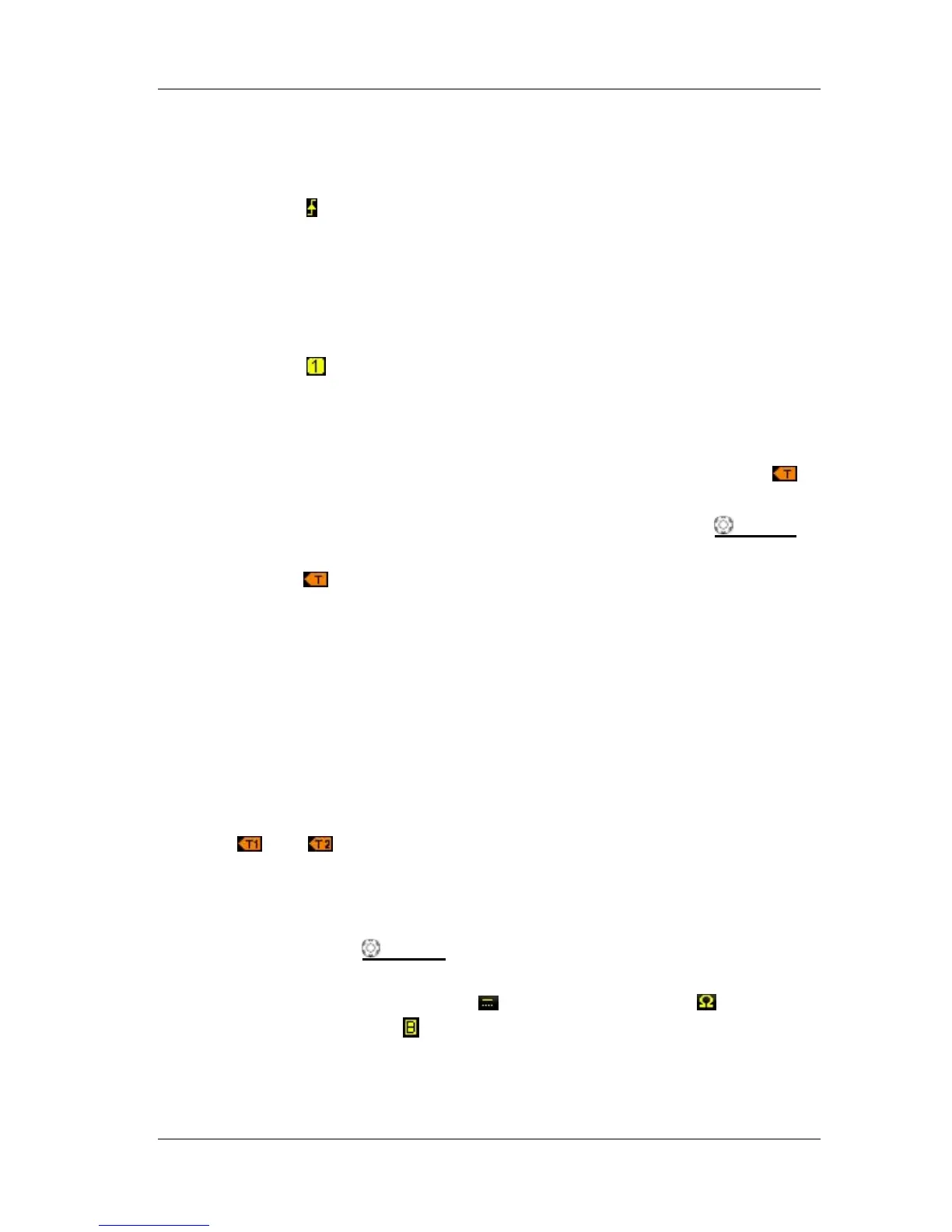
9. Trigger Type
Display the currently selected trigger type and trigger condition setting.
Different labels are displayed when different trigger types are selected.
For example:
represents triggering on the rising edge in “Edge” trigger.
10. Trigger Source
Display the trigger source currently selected (CH1, CH2, EXT, EXT/5, AC Line or
D0-D15). Different labels are displayed when different trigger sources are
selected and the color of the trigger parameter area will change accordingly.
For example:
denotes that CH1 is selected as the trigger source. Note:
EXT/5 is only applicable to MSO2000A and MSO2000A-S models oscilloscopes.
11. Trigger Level
When the trigger source is set to CH1 or CH2, the trigger level label
is
displayed at the right of the screen and the trigger level value is displayed at
the upper-right corner of the screen. When using TRIGGER
LEVEL to
modify the trigger level, the trigger level value will change with the up and
down of
.
When the trigger source is set to EXT or EXT/5, the trigger level value is
displayed at the upper-right corner of the screen. No trigger level label is
displayed.
When the trigger source is set to AC Line, no trigger level value and trigger
level label is displayed.
When the trigger source is set to D0 to D15, the trigger threshold is
displayed at the upper-right corner of the screen. No trigger level label is
displayed.
In Runt trigger, Slope trigger and Windows trigger, two trigger level labels
(
and ) are displayed.
12. CH1 Vertical Scale
Display the voltage value per grid of CH1 waveform vertically.
Use VIRTICAL
SCALE of CH1 to modify this parameter.
The following labels will be displayed according to the current channel
setting: channel coupling (e.g.
), input impedance (e.g. ) and
bandwidth limit (e.g.
).
 Loading...