2. Digital Channel Label/Waveform
The logic high level of the digital waveform is displayed in blue and the logic low
level in green (correspond to the color of the channel label). Its edge is
displayed in white. The label and waveform of the digital channel currently
selected are displayed in red. Note: This function is only applicable to
MSO2000A and MSO2000A-S models oscilloscopes.
3. Status
Available states include RUN, STOP, T’D (triggered), WAIT and AUTO.
4. Horizontal Time Base
Represent the time per grid on the horizontal axis on the screen.
Use HORIZONTAL
SCALE to modify this parameter. The range
available is from 1.000 ns to 1.000 ks (for 200 MHz bandwidth oscilloscope,
the range available is 2.000 ns to 1.000 ks; for 100 MHz and 70 MHz
bandwidth oscilloscope, the range available is 5.000 ns to 1.000 ks).
5. Sample Rate/Memory Depth
Display the current sample rate and memory depth of the oscilloscope.
Use HORIZONTAL
SCALE to modify this parameter.
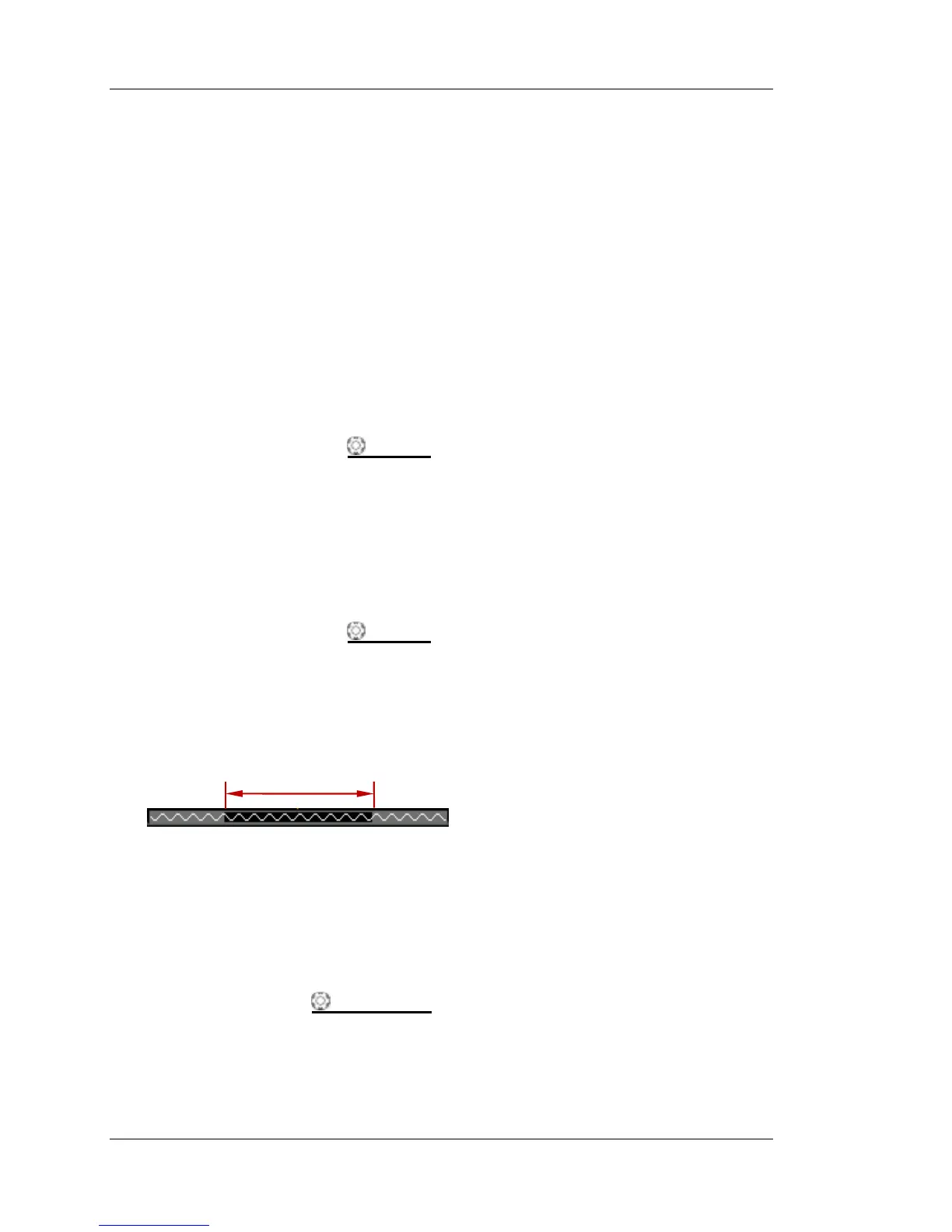
6. Waveform Memory
Provide the schematic diagram of the memory position of the waveform
currently on the screen.
7. Trigger Position
Display the trigger position of the waveform in the waveform memory and on
the screen.
8. Horizontal Position
Use HORIZONTAL
POSITION to modify this parameter. Press down the
knob to automatically set the parameter to zero.
waveform on the screen
 Loading...