10
INSTALLATION INSTRUCTION
The welding equipment is equipped with power voltage compensation device. It keeps the machine
working normally when power voltage fluctuates ±15% of rated voltage.
When using long cable, in order to reduce voltage drop, big section cable is suggested. If the cable is
too long, it will affect the performance of arcing and other system functions, it is suggested to use the
recommended length.
1. Make sure the intake of the machine is not covered or blocked to avoid the malfunction of the
cooling system.
2. Make sure the earth end of power interface has been reliably and independently grounded.
Installation Procedures:
Installation for MIG process
1) Connect the gas cylinder to the regulator. Select correct shielding gas for the application.
2) Fit the wire spool to the machine. Select
correct welding wire for application.
3) Select the appropriate feed roller to suit the
wire being used.
- V groove for use with solid carbon
manganese and stainless steel.
- U groove for use with soft wires such as
aluminum.
4) Loosen the wire feed tension screws an
insert the wire. Refit and tension roller
ensure the wire is gripped sufficiently so a
not to slip but avoid over-tightening as this can affect feed quality and cause wire feed components
to wear rapidly.
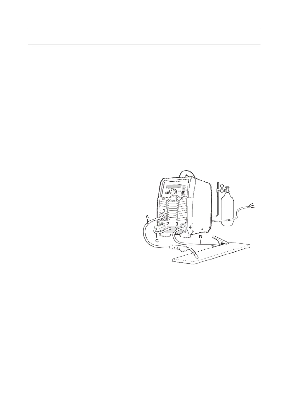
5) Fit and tighten the torch (A) on the output connection (1). Ensure correct torch liner and contact tip
are selected.
6) Selectthecorrectpolarityforthetypeofwireusedasindicatedontheconsumable packaging.
This is achieved by swapping the polarity terminal wires. For most solid wires the terminal should
be set as torch positive.
For torch positive, plug the short mechanical connector (C) on the front panel into the positive
terminal (2) and the work return lead (B) into the negative terminal (4).
For torch negative, plug the short mechanical connector (C) into the negative terminal (4), and
the work return lead (B) into the positive terminal (2).