10 Fan Convector Manual
13. Adjust the Low fire seng by using the “UP”(▲to
increase) and the “DOWN” (▼to decrease)
buons to adjust the manifold pressures per the
table below.
14. Press the Test switch (FIGURE 2) again to place
the unit in High fire mode. “PH” will appear on
the display.
15. Adjust the High fire seng by using the “UP”(▲to
increase) and the “DOWN” (▼to decrease)
buons to adjust the manifold pressures per the
table below.
16. Press the “ON/OFF” buon to cease operaon.
(The unit will not revert to its normal state unless
the “ON/OFF” buon is pressed.)
17. Press the “ON/OFF” buon once again to
complete procedure.
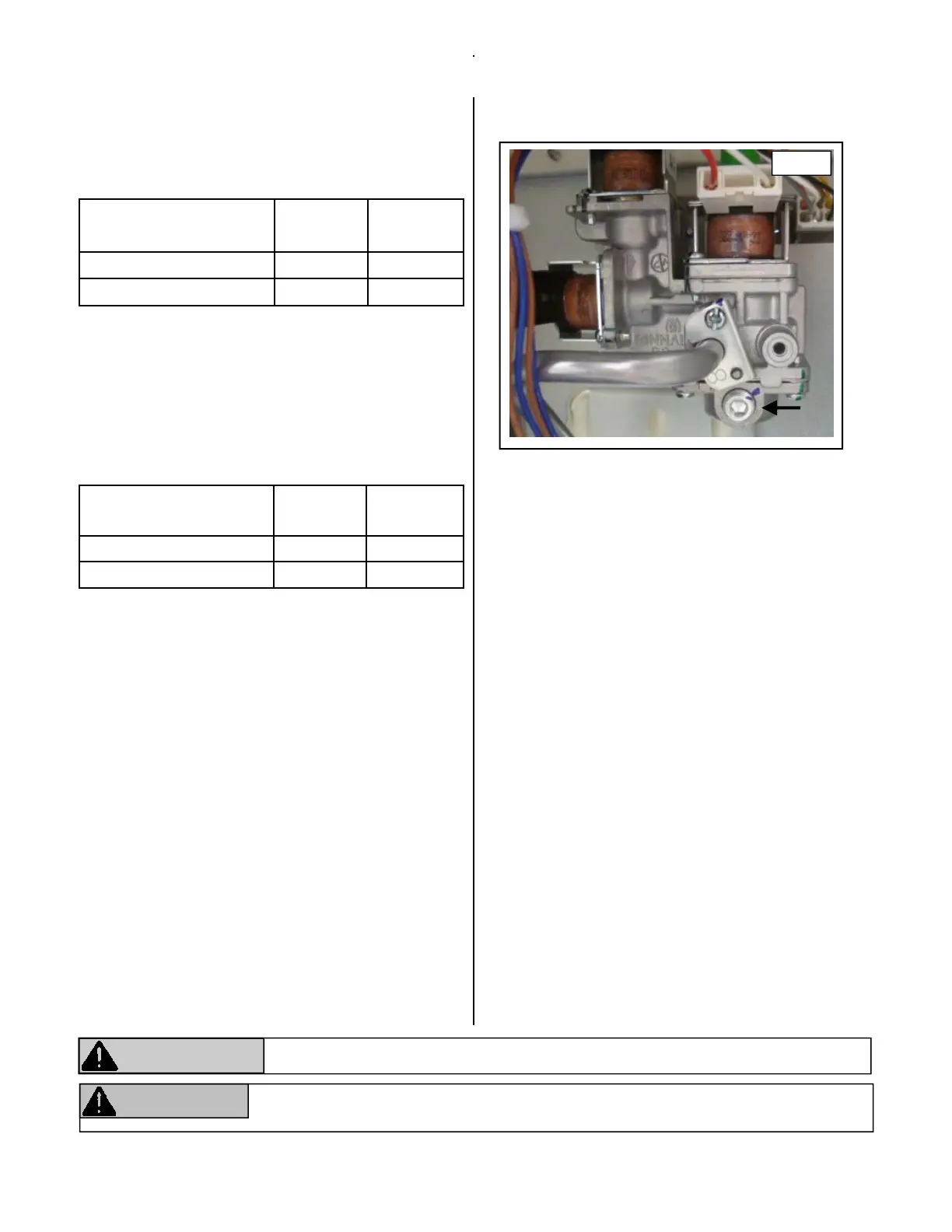
18. Turn off gas supply. Remove manometer and
reinstall test port plug. (FIGURE 3)
19. Turn on gas supply. Operate the unit normally
checking for normal operaon and gas leaks.
20. Turn off gas and power supply to unit.
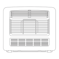
21. Reinstall front panel. (FIGURE 1)
22. Turn on gas and power supply and place unit in
normal working condion.
Low pressure
2,001‐5,200
Natural
Gas
Propane
Gas
FC510 0.75” W.C. 1.31” W.C.
FC824 0.61” W.C. 1.17” W.C.
High pressure
2,001‐5,200
Natural
Gas
Propane
Gas
FC510 1.8” W.C. 3.2” W.C.
FC824 3.4” W.C. 6.3” W.C.
Failure to properly follow these instrucons may result in the unit shung down.
ATTENTION
WARNING
Failure to correctly reassemble the components according to these instrucons may
result in a gas leak or explosion.
FIGURE 3
HighAltudeInstallaons

 Loading...