28
Communication cable
Wired remote controllers operate at an extra low voltage (12 Volts DC) which is supplied from the water heater. A 10m
long communication cable is supplied for connection to the water heater. It is possible to prolong the communication
cable by using a similar one, up to a total max length of 50m. When connecting the cables to remote controller the
polarity is not important: either colour wire can be connected to either terminal.
It is not recommended to install the communication cable near by house electric cables: interference may easily
happen causing system malfunctions. In these cases we recommend to use proper shielded cables.
board side and on the remote control side:
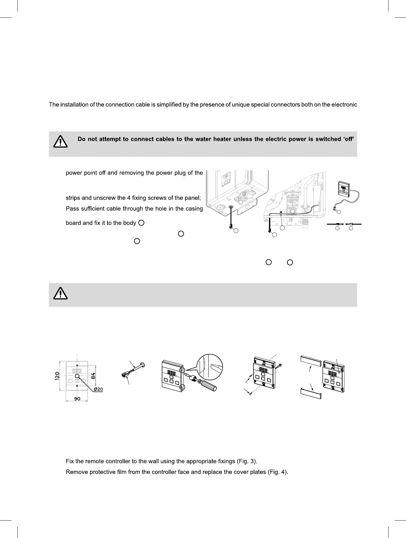
Installation procedure (appliance side):
otherwise damage to electrical components may occur.
1. Isolate the electric power supply by switching the
water heater from the electric power socket.
2. Remove the front panel: remove the grey plastic side
3.
(Fig. 1); connect the terminal end to the electronic
C
(Fig. 2);
4. Connect the other terminal of the cable
A
to the
remote control connector
B
(Fig. 3)
5. Fix the front panel back.
When connecting more remote controllers it is necessary to cut the connectors
A
and
B
, and to use a common
electrical terminal block (optional)
The additional remote controls must be electrically connected in parallel: a series connection
causes the system to malfunction and can damage the components of the appliance.
Standard Remote Controller (MC-601) Installation
1. Determine the most suitable position.
2. Mark and drill 3 holes (mounting and cable access) for remote controller dimensions.
3. When running cable through the access hole ensure the connector end of the cable is located nearest to the
remote controller (Fig. 1).
4. Carefully remove the cover plates from the remote controller, using a screw driver (Fig. 2).
5. Connect the cable to the remote controller. Feed any excess cable lengths into the wall cavity to avoid the
pinching of cables between the wall and the remote controller.
6.
7.
Connector
Controller Cable
Screws
Film
Fig. 1 Fig. 2 Fig. 3 Fig. 4
Cover
Plates
A
B
C
B
A
A
Fig. 1 Fig. 2
Fig. 3
Enfocus Software - Customer Support
 Loading...