Rinnai 10 RDV 600_700ER IM
GAS SUPPLY
Gas pipe sizing MUST consider the gas input to this appliance as well as all other gas appliances
in the premises. The gas meter and regulator MUST be specied for the total gas rate.
A suitable sizing chart such as the one in AS/NZS 5601 should be used.
The use of rubber hose for any gas connection to a xed appliance is NOT authorised by the
manufacturer.
Conrm correct gas type (see labels located on top or rear panels). Refer to local gas authority
for conrmation of gas type if you are in doubt.
Installation of Consumer Piping
The gas supply (consumer piping), termination is inside the heater and enters
through the rear of the appliance.
Refer to the dimensional drawings on page 34 for appliance gas inlet location
and other relevant dimensions.
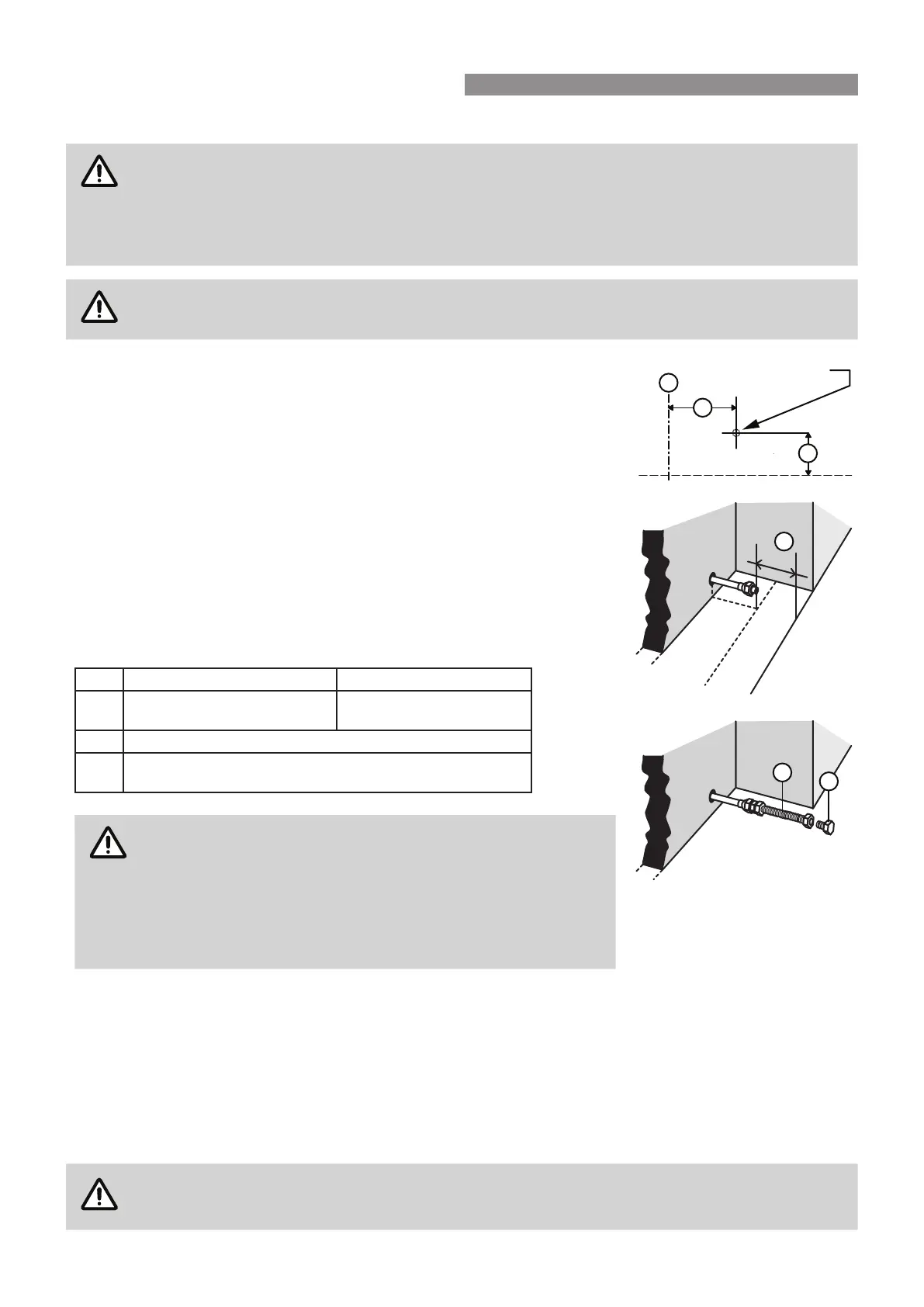
Mark o the location for the vertical centre line
(
1
)
of the heater enclosure (inbuilt
installations) or heater (freestanding installations).
To the right of the vertical centre line
(
1
)
, mark o both the vertical
(
2
)
and
horizontal
(
3
)
location for the gas supply penetration (consumer piping). For
measurements refer to the Gas Supply Dimension Table below.
The length of the gas supply (consumer piping) termination
(
4
)
is measured from
the front of the enclosure.
Gas Supply Dimension Table
RDV600ER RDV700ER
(
2
)
265 mm to the right of the
appliance centre-line
312 mm to the right of the
appliance centre-line
(
3
)
18mm from base of enclosure
(
4
)
Consumer piping to be terminated 295 mm from the front of
enclosure.
For masonry replace installations:
Gas supply dimension
(
4
)
MUST include the thickness of an
inll panel (when tted). A standard Rinnai inll panel adds
2mm to the front of the enclosure.
For false replace installations:
Gas supply dimension
(
4
)
MUST include the thickness of the
cladding to be used.
Once the consumer piping has been terminated to the above requirements the supplied exible gas connection
(
5
)
may then be tted.
Purging Gas Supply
Foreign materials and debris such as swarf, lings, etc. MUST be purged/removed from the gas supply, failure to
do so may cause damage to the gas control valve causing it to malfunction.
Leak Testing the Connection
With the supplied plug inserted into the end of the exible gas connection leak test all joints.
Use a soapy solution to test all gas connections. If a leak is present bubbles will form at the leak
point. When nished remove any residue with a rag. Prevent any soapy solution from coming in
contact with electrical components.
FRONT OF ENCLOSURE
LOSURE
REAR OF
ENC
4
1
2
Gas supply location
3
5
6
Gas supply pressure
to be 1.13 to 2.75 kPa
SUPPLY CONNECTIONS
 Loading...