Rinnai 25 RDV 600_700ER IM
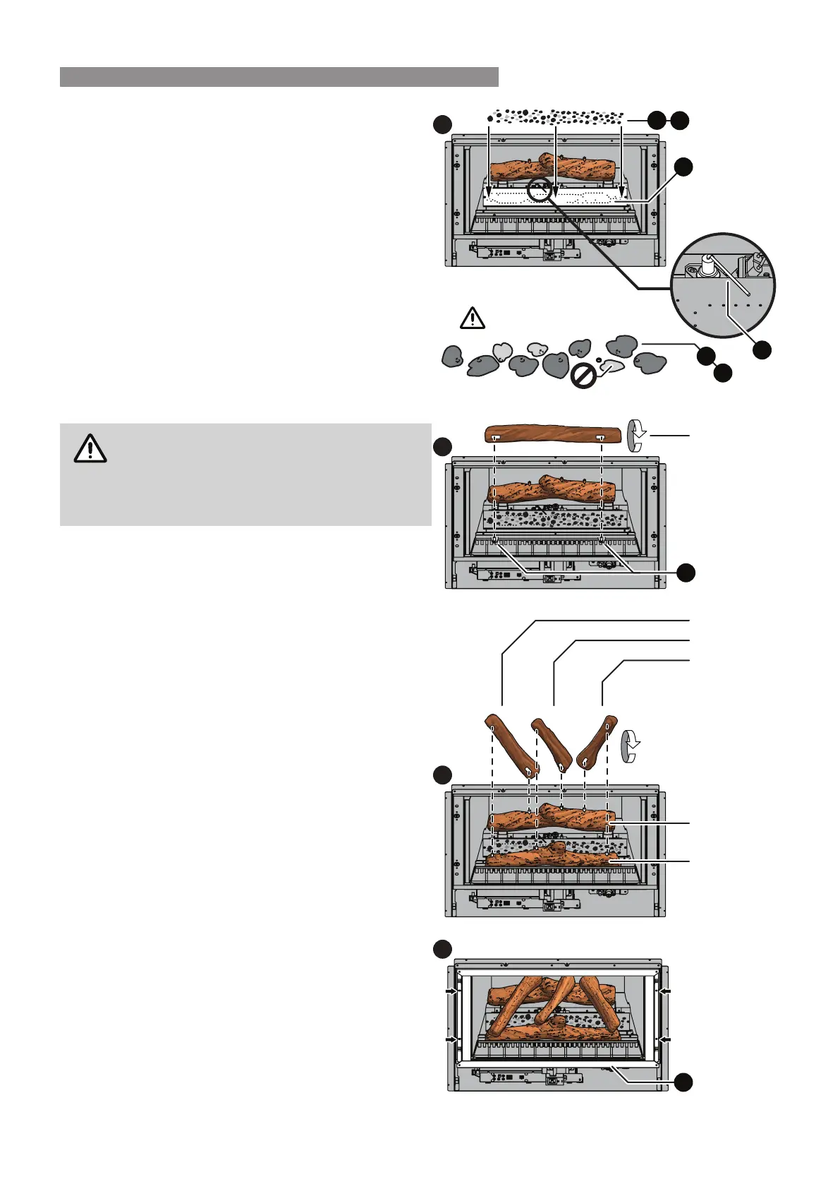
Step 5. Charcoal Bed Installation
The charcoal bed is placed directly onto the burner (I).
For the RDV700 you will need use both bags of the black
burner granules (F), while for the RDV600 approximately
only one and three quarter bags worth.
The brown burner bre (H) will need to be pinched into
approximately ten cent piece sized tufts.
To produce the best ame eect results, in a random
manner carefully place the black burner granules (F) and
the brown burner bre tufts (H) loosely across the entire
surface of the burner (I).
Allowing the burner media to sit over and around the
burner ports, will ensure that the ames from the gas jets
are diused, which reduces any 'candling' eect of the
ame while also enhancing the realistic log burning look
of the heater.
DO NOT force any granular or brous
materials into the burner ports or completely
block any of the burner ports.
Keep the ame probe (J) free of any direct
contact with any of the burner media.
Step 6. FRONT log Installation
Identify the “FRONT” log and then carefully remove it
from the protective packaging.
Locate the two slots in the base of the log and carefully
place these over the positioning pins (K) which are part
of the stone guard (C), ensuring that the detailed surface
of the log is facing out to the front.
Step 7. LEFT, MIDDLE & RIGHT log Installation
Identify the “LEFT” log and then carefully remove it from
the protective packaging.
Locate the two slots in the base of this log, noting that the
long slot is the rear most slot, and carefully place these
slots over the set of two left outermost positioning pins
located on both the “FRONT” and “REAR” logs.
Identify the “MIDDLE” log and then carefully remove it
from the protective packaging.
Locate the two slots in the base of this log, noting that the
long slot is the rear most slot, and carefully place these
slots over the set of two central positioning pins located
on both the “FRONT” and “REAR” logs.
Finally carefully remove the “RIGHT” log from the
protective packaging.
Locate the two slots in the base of this log, noting that the
long slot is the rear most slot, and carefully place these
slots over the set of two right outermost positioning pins
located on both the “FRONT” and “REAR” logs.
Step 8. Replacing the Burner Box Glass
Replace burner box glass panel assembly in the reverse
sequence to that explained in Step 1. on page 24.
6
5
F
H
F
H
FRONT log
7
LEFT log
MIDDLE log
RIGHT log
8
A
COVERING PORTS
I
K
FRONT log
REAR log
J
BURNER MEDIA INSTALLATION
 Loading...