Rinnai 16 RDV 600_700ER IM
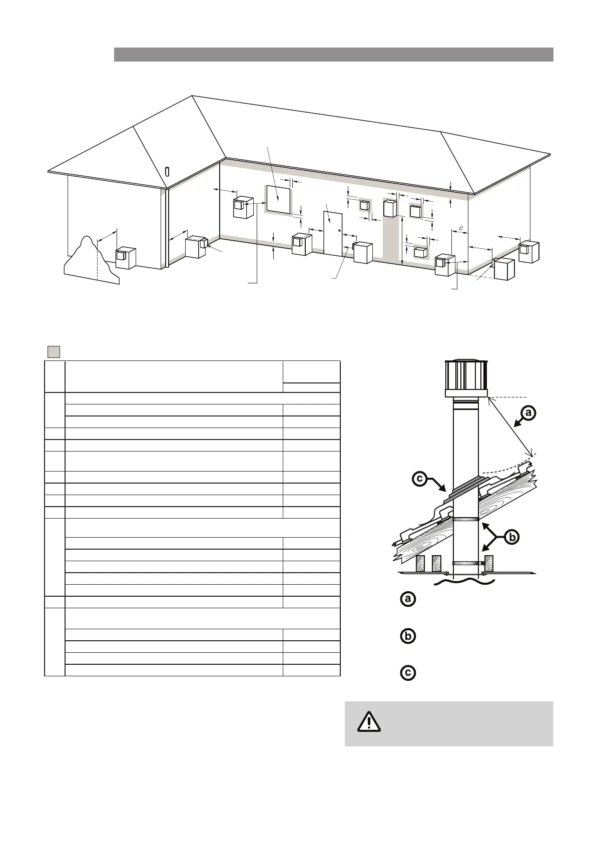
FLUE TERMINAL CLEARANCES
(
EXTRACT FROM AS/NZS 5601
)
Min. Clearances
(mm)
Natural Draught
• Appliances up to 50 MJ/h input
300
• Appliances over 50 MJ/h input
500
003* ecafrus rehto ro ynoclab a evoba ,dnuorg eht morFb
005* renroc lanretxe ro llaw nruter a tnorFc
d
From a gas meter (M) (see 5.11.5.9 for vent terminal location of regulator )
(see Table 6.6 for New Zealand requirements)
1000
e
From an electricity meter or fuse box (P) †
500
epip lios ro epip niard a morFf
g
Horizontally from any building structure* = or obstruction facing a terminal
500
h
From any other flue terminal , cowl, or combustion air intake †
500
• Appliances up to 150 MJ/h input *
500
• Appliances over 150 MJ/h input up to 200 MJ/h input *
1500
• Appliances over 200 MJ/h input up to 250 MJ/h input *
1500
• Appliances over 250 MJ/h input *
1500
• All fan-assisted flue appliances , in the direction of discharge
-
0051rewolb aps a gnidulcni ,telni ria lacinahcem a morFk
051tupni rh/JM 05 ot pu sretaeh ecapS •
• Other appliances up to 50 MJ/hr input
500
• Appliances over 50 MJ/h input and up to 150 MJ/h input
1000
• Appliances over 150 MJ/h input
1500
1
Where dimensions c, j or k cannot be achieved an equivalent horizontal distance
measured diagonally from the nearest discharge point of the terminal to the opening
may be deemed by the Technical Regulator to comply.
2
See Clause 6.9.4 for restrictions on a flue terminal under a covered area.
3
See Figure J3 for clearances required from a flue terminal to an LP Gas cylinder.
A flue terminal is considered to be a source of ignition.
4
For appliances not addressed above acceptance should be obtained from the
Technical Regulator.
metI.feR
a
Below eaves, balconies and other projections:
FIGURE 6.2 (in-part) MINIMUM CLEARANCES REQUIRED FOR FAN-ASSISTED FLUE TERMINALS,
ROOM-SEALED APPLIANCE TERMINALS AND OPENINGS OF OUTDOOR APPLIANCES
* - unless appliance is certified for closer installation
n
j
Horizontally from an openable window, door, non-mechanical air inlet, or any other opening into a
building with the exception of sub-floor ventilation:
Vertically below an openable window, non-mechanical air inlet, or any other opening into a
building with the exception of sub-floor ventilation:
NOTES:
† - Prohibited area below electricity meter or fuse box extends to ground level.
150
S had ing in d ica te s pro hibit ed area fo r flue ter minals
LEGEND:
I = Mec h ani cal ai r inl et
M = G as me te r
P = El e ctr icit y me ter or fu se box
S = Str ucture
T = Fl ue te rminal
Z = Fa n -as sis ted app lia nce o nly
Direction of
discha rge
See N ote 1
See N ote 1
Opening int o
a building
T
T
T
T
T
T
T
C
M
d
d
e
e
h
j
j
j
n
b
f
a
h
P
Z
S
k
k
g
g
g
I
T
Door
Minimum clearance 500 mm
to nearest part of roof.
Minimum clearance 25 mm
to combustible materials.
Decktite or lead collar flashing.
This appliance is a natural draft
appliance and does not contain
a combustion fan.
FLUEING
 Loading...