AGM - Installation and Programming Instructions 5
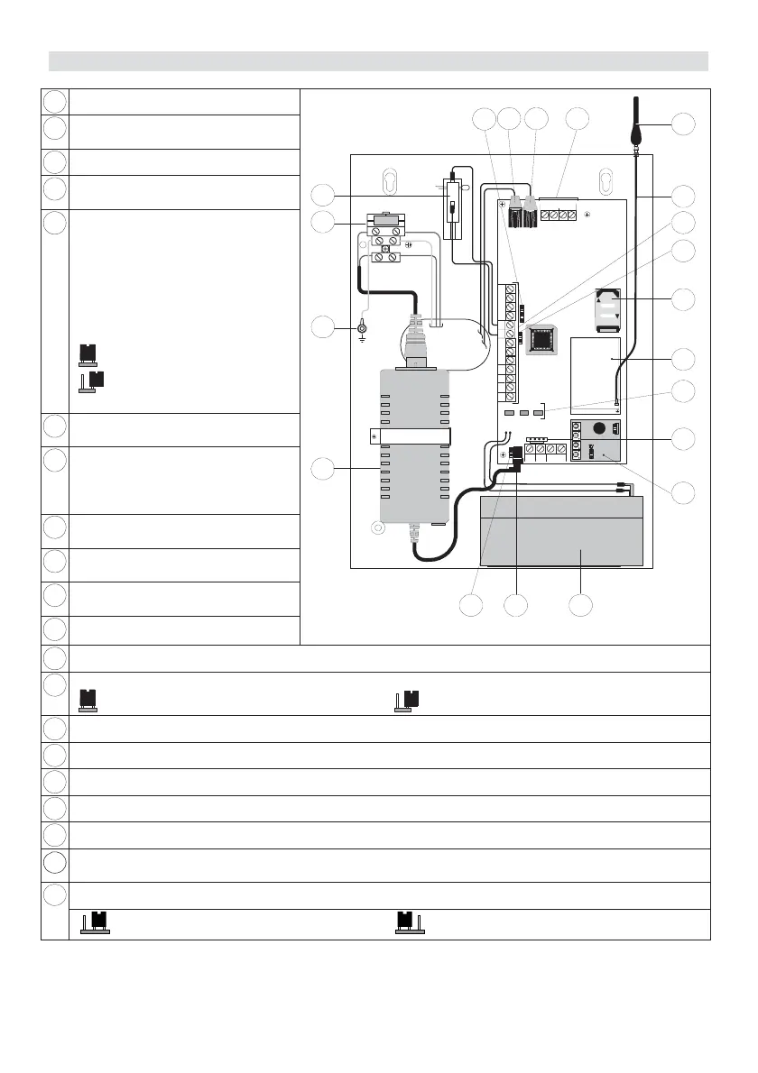
2. AGM Components
1
Tamper Switch (NC)
2
Mains connectors (fuse
protected)
3
Ground: Box ground connector
4
Power Transformer:
(14.5VDC/0.8A)
J14: Battery discharge
Protection Circuit Jumper. If AC
power outage occurs, the AGM
automatically disconnects the
battery when the battery voltage
drops below 10.5VDC, in order
to protect the battery from deep
discharge.
On - No protection
5
Off (Default) - Battery
protection is activated
6
14.5VDC/0.8A Power socket
(from Transformer)
7
Backup Battery:
12VDC/1.2A/H
Sealed Lead - Acid
Rechargeable Battery
8
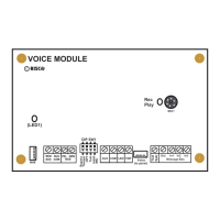
Plug on Voice Module
(optional)
9
J10: PC Connector (via RISCO
Group's cable adaptor)
10
GSM status LEDs: (Power,
GSM, Low Battery)
11
GSM Industrial Module
BUS
+12 V
GND
LOCK
OPE N
RED
BLK
YEL
GRN
LD1 LD3 LD2
1
L. BA T
GS M
POWER
J14
1234 C
PLAY R EC
4
8
9
10
11
12
13
14
15
16
1718
19
20
3
765
NL
2
FUSE : T 0.5A 250V
J15
J13
COMINPUT TMP
N.C N.O
UØ1 UØ 2 UØ3 UØ4 AUX
SET LINE
PHONE
100- 240V~ 50/ 60 Hz
MAX:0 .4A
Figure 1. AGM Components
12
SIM Card Socket
13
J13: Tamper Jumper
Tamper is not used (Default) - Tamper is used
14
Terminal block (See terminal block wiring section on page 8)
15
GSM Antenna Cable
16
GSM Antenna
17
Telephone Line Connection Terminals (in parallel to the phone jack connectors)
18
Telephone Connector - Line: From wall outlet
19
Telephone Connector - Set: To security panel or to premises telephone in absence of control
panel.
J15: Used to set Negative (-) or positive (+) remove of inputs 1 - 4 (see page 8).
20
Negative Remove (Default) Positive Remove