8 AGM - Installation and Programming Instructions
5. Insert external cables (GND, Power, and Phone lines) through the cable
passage (6, Figure 3).
6. Align the AGM with the mounting holes and fasten it firmly to the wall with
all four supplied screws (1, Figure 3).
7. Attach the AGM antenna.
8. Connect the AGM backup battery cables to the backup battery.
9. Connect power cables from mains to the power/grounding terminals (2,
Figure 1).
10. Install the front cover in its place (in a reverse sequence of the removal
(see Figure 3).
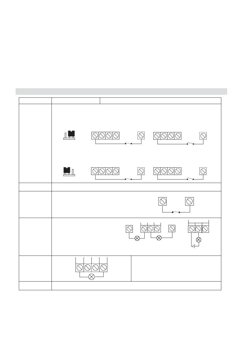
4. Wiring the AGM
Connector Wiring Diagram Description
INPUT
(1, 2, 3, 4)
The Inputs polarity is defined by jumper J15.
Negative remove: Connect the detector/s to the required Input/s
terminal/s (Input 1, 2, 3 or 4) and the COM (0V) terminal.
NR (Negative Remove)
(Default)
1234
INPUT
COM
NO
1234
COM
NC
INPUT
Positive remove: Connect the detector/s to the required Input/s
terminal/s (Input 1, 2, 3 or 4) and the AUX (14.4VDC) terminal.
PR (Positive Remove)
1234
INPUT
AUX
NO
1234
INPUT
AUX
NC
COM 0V
TMP
Tamper alarm activates when
the front cover is open or the
entire box is removed from the
wall.
COM TMP
NC
UO1
Relay (3A)
NC: Normally closed contact
C: Common contact
NO: Normally open contact
COM
AUX
N.C C N.O
UO1
N.C C N.O
UO1
External power supply
UO2 to UO4
(100mA)
UO2 UO3 UO4 AUX
Wire the devices that you want to
activate to the outputs terminals
AUX 14.4VDC