Genisys Dock Leveler Owners Manual
18 Pub. No. 1185-R1 - August 2004
HYDRAULIC VALVE ADJUSTMENTS
SHUTTLE VALVE ADJUSTMENT
(CONTROLS LEVELER DESCENT)
Note:
• Check oil level before making any adjustments.
Note:
Valve Position Illustrated Represents The Nominal
Factory Setting Of 3-1/2 Turns Out From The Fully
Turned In Position
1. Leveler must be adjusted to lower, from full raised
position with lip extended to the header stops, in 8 to
12 seconds.
2. Remove protective cap and O-ring. Loosen locknut;
without turning valve body or adjustment screw. Turn
adjustment screw to vary platform lowering speed.
See Figures 20 and 21.
3. Adjustments should be no more than 1/8 turn
increments.
4. Loosen adjustment screw to decrease platform
speed while lowering (excessive loosening can
eliminate platform lowering).
5. Tighten adjustment screw to increase platform speed
while lowering (velocity fuse may lock-up as a result
of increased platform speeds while lowering).
6. Tighten locknut without turning valve body or
adjustment screw.
7. Reinstall o-ring and protective cap and tighten cap.
8. Re-test the unit several times to verify the setting.
HYDRAULIC LEVELER ADJUSTMENTS CONT.
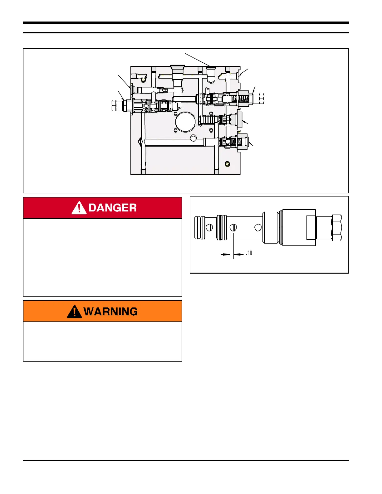
RAMP CYLINDER PORT
LIP CYLINDER PORT
PILOT OPERATED
CHECK VALVE
ADJUSTABLE
RELIEF VALVE
ADJUSTABLE
SEQUENCE
VALVE
ADJUSTABLE
SHUTTLE
VALVE
PILOT TO
CLOSE CHECK
VALVE
• DO NOT operate leveler with anyone standing on or
in front of the lip.
• NEVER go under the hydraulic leveler platform or lip
without installing the Maintenance Support.
• Make sure that the leveler power is locked out and
tagged out according to OSHA regulations and
approved local codes.
Figure 21 - Shuttle Valve Nominal Setting
Figure 20 - Power Unit End Head
• Shuttle valve is factory adjusted and sealed.
• Adjustments to be completed by trained technician
only.
 Loading...