10 Rittal Blue e+ fan-and-filter unit assembly and operating instructions
EN
Commissioning
1.
2.
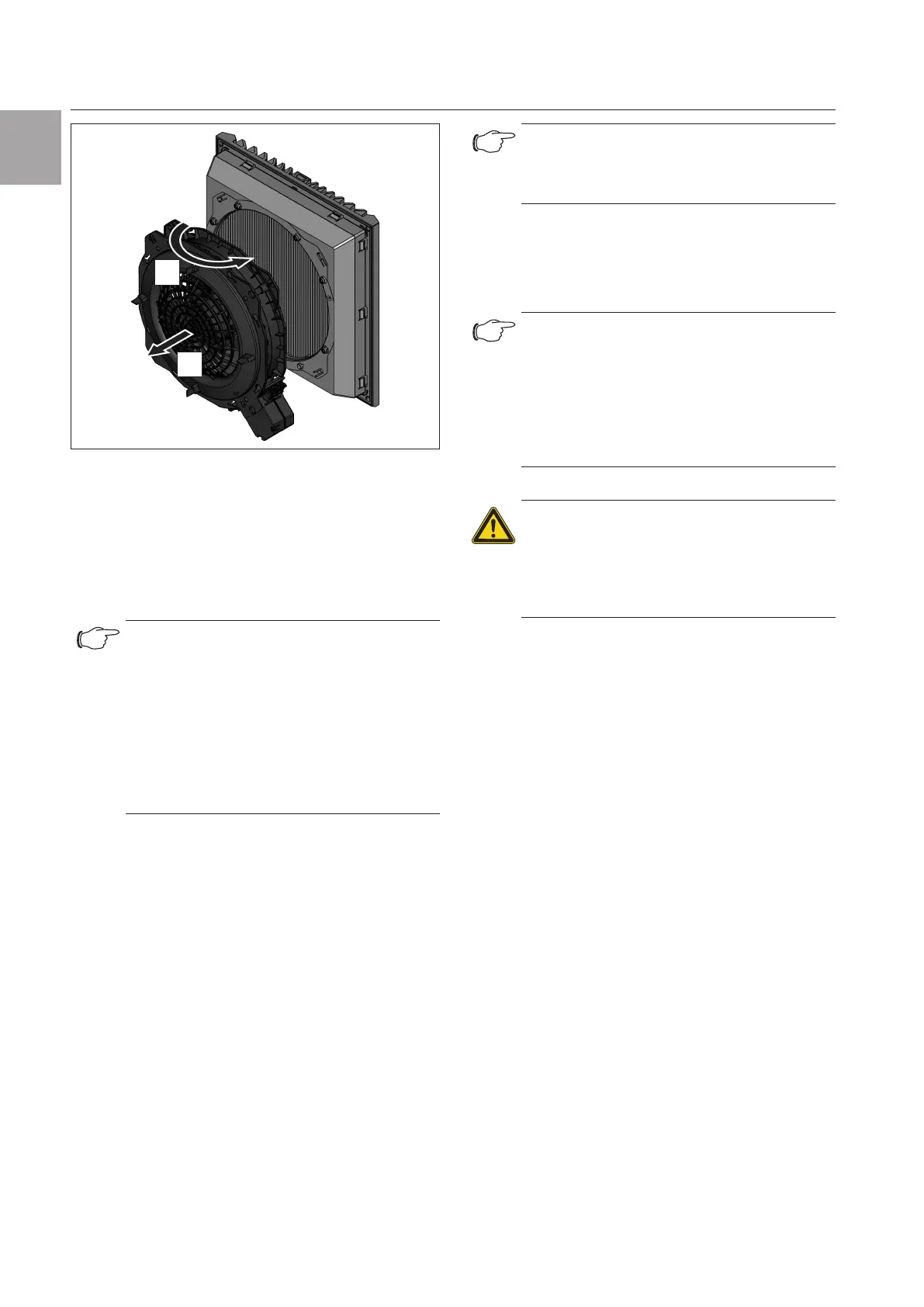
Fig.13: Changing the direction of airflow
◾ Place the fan housing back on the filter box in this
position and lock the bayonet connection.
This is done in the same way as described in
section5.2 "Rotating the voltage connection",
page8.
◾ Please also observe the instructions outlined under
section4.2.1 "General", page5.
Note:
If the direction of airflow is changed, the fan-
and-filter unit blows air out of the enclosure.
◾ In this case, ensure that the fan-and-filter
unit can draw sucient air freely through
the outlet filter(s).
Otherwise there is a risk of an air short-cir-
cuit and, in the event of exposure to water,
of water droplets being drawn into the
enclosure.
6 Commissioning
The fan-and-filter unit operates automatically, in other
words, the fan will start up once the power has been
switched on.
Depending on the model, the following voltage variants
are supported:
– 24 V, DC
– 115 V, 1~
– 230 V, 1~
– 400/460 V, 3-phase
7 Installing and changing the filter
The fan-and-filter unit and outlet filter are supplied as
standard with a pleated filter for pre-filtering dry coarse
dust and lint in the ambient air.
Note:
A chopped-fibre filter is installed as stand-
ard on the 3237.xxx and EMC fan-and-filter
units.
The filter should be checked at regular intervals in
accordance with the level of dust exposure (recom-
mended: at the latest after 2,000 operating hours) and
replaced as necessary.
Note:
Use only original Rittal filters which bear the
Rittal logo in order to safeguard the desig-
nated protection category, air throughout
and operating approvals.
The pleated filter supplied for the fan-and-
filter unit must be removed and disposed of
when a chopped-fibre filter is deployed.
Risk of injury!
Only change the filter mat while the fan
rotor is stationary.
Never insert your fingers into the fan
rotor. Filter installation or replacement
only when de-energised.
To insert or replace the filter, proceed as follows (direc-
tion of airflow: drawing from outside and blowing into
the enclosure).
7.1 Replacing the pleated filter
◾ To unlock the louvred grille, press the function logo
from above (see fig.17).
◾ Fold the louvred grille down to an angle of approx.
90°.
◾ Remove the soiled pleated filter or the soiled
chopped-fibre filter mat.
◾ Place the new pleated filter in the louvred grille.
The "Top" logo indicates the insertion direction (see
fig.14).