Rittal Blue e+ fan-and-filter unit assembly and operating instructions 7
EN
Carrying out the electrical connection
– IP56 by using a hose-proof hood.
Note:
To increase the protection category, a pleat-
ed filter or hose-proof hood must be used
for the fan-and-filter unit and outlet filter.
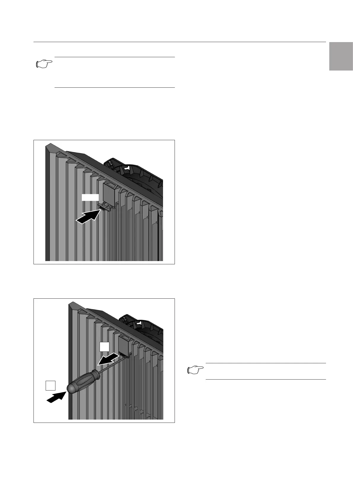
4.3.3 Safety clip
To prevent undesired opening of the louvred grille in
special situations, the safety clip (see section13 "Ac-
cessories") can be mounted below the function logo
without tools. This can be used, for example, during
tests or for transport.
Click!
Fig.3: Inserting the safety clip
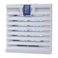
◾ Use a small screwdriver to lever out the safety clip if
it needs to be removed, e.g. to remove the louvred
grille.
1.
2.
Fig.4: Removing the safety clip
4.4 Notes on electrical connection
When performing the electrical connection, it is impor-
tant to observe all valid national and regional regula-
tions as well as the provisions of the responsible power
supply company. Electrical connection must only be
carried out by a qualified electrician who is responsible
for compliance with the existing standards and regula-
tions.
4.4.1 Connection data
– The voltage and frequency of the connection must
correspond to the values stated on the rating plate.
– Electrical connection and any repairs may only be
carried out by authorised specialist personnel.
– Use only original spare parts!
– For 1~ and 24 V (DC) fans, install the pre-fuse pre-
scribed on the rating plate (circuit-breaker or slow
fuse) to protect against short-circuiting.
– With the rotary current variant, install the pre-fuse
prescribed on the rating plate or a circuit-breaker/
back-up protection to protect against short-circuiting,
and set it to the prescribed rating value.
– The direction of airflow and the direction of rota-
tion are each marked on the motor housing with an
arrow.
– If a phase is missing, the fan will not start. If the rota-
ry field is incorrect, the fan will run backwards.
4.4.2 Overvoltage protection and supply line
load
The unit does not have its own overvoltage protection.
Measures must be taken by the operator at the supply
end to ensure eective lightning and overvoltage pro-
tection. The mains voltage must not exceed a tolerance
of ±10%.
4.4.3 PE conductor connection
The PE conductor connection must be connected to
the PE conductor system of the overall system.
5 Carrying out the electrical con-
nection
5.1 Connecting the power supply
◾ Complete the electrical connection by following the
wiring plans.
Note:
For technical data, refer to the rating plate.
◾ Insert the connection cable with wire end ferrules into
the screwless spring terminals.
Choose an appropriate pre-fuse according to the line
cross-section (2 x 0.75 – 2.5 mm² multi-wire, 2 x 1.5
– 2.5 mm² fine-wire soldered).