6 Rittal Blue e+ fan-and-filter unit assembly and operating instructions
EN
Assembly and connections
– The fan-and-filter and outlet filter must always be
mounted on an enclosure in order to ensure air
exchange.
Note:
The outlet filter should be at least the same
size as the fan-and-filter unit.
– The enclosure must be sealed on all sides (IP54). If
the enclosure has a leak, unfiltered, contaminated air
may enter the enclosure, depending on the direction
of airflow of the fan.
– To allow the louvred grille to be opened without prob-
lem when the fan-and-filter units are bayed vertically,
a minimum separation should be observed.
– This is either 15 mm measured between drilling tem-
plates or between the associated mounting cut-outs
in accordance with the following table:
Model No.
Separation between two
mounting cut-outs
3237.xxx 39.5 mm
3238.xxx 39 mm
3239.xxx 42 mm
3240.xxx 46 mm
3243.xxx 46 mm
Tab. 2: Separation between two mounting cut-outs
4.2.2 Layout of the components in the enclosure
◾ Observe the air flows from the internal fans of in-
stalled electronic components.
For installation, it is important to ensure that the air-
flows of fans and built-in electronic components do not
have a negative influence on one another (air short-cir-
cuit). To ensure unimpeded air circulation, a minimum
distance must be maintained between the fan and the
component that corresponds to half the fan-and-filter
unit's mounting cut-out.
4.3 Fitting the fan-and-filter unit or outlet
filter
The fan-and-filter unit or outlet filter is mounted on a
vertical panel of the enclosure:
◾ For this purpose, the appropriate door, side or rear
panel must be cut out using the supplied drilling
template.
The fan-and-filter unit is generally fitted in the lower part
of the enclosure, and the outlet filter in the upper part.
4.3.1 Cutting out the enclosure
◾ Stick the self-adhesive drilling template supplied to
the envisaged position on the door, side or rear panel
of the enclosure.
Lines indicating the dimensions of cut-outs and drilling
specifications for mounting and fixing of the fan (only
necessary for sheet metal thickness 2.5 mm and
above) are to be found on the drilling template. See
also fig.20 and fig.22, page21.
◾ Make the cut-outs including the line width as per the
drilling template.
Risk of injury!
Carefully deburr all cut-outs to prevent
injuries caused by sharp edges.
◾ Deburr the cut-outs.
4.3.2 Fitting the fan-and-filter unit
– The fan may be fitted without tools, by simply snap-
ping into the preconfigured mounting cut-out.
– Make sure that the clips have snapped into place
properly to guarantee secure mounting.
– From a sheet metal thickness of 2 mm, the clips
should be pressed in individually.
– From a sheet metal thickness of 2.5 mm, the fan-
and-filter unit must be screw-fastened in addition
(tightening torque, see section 11 "Cut-out/drilling
dimensions").
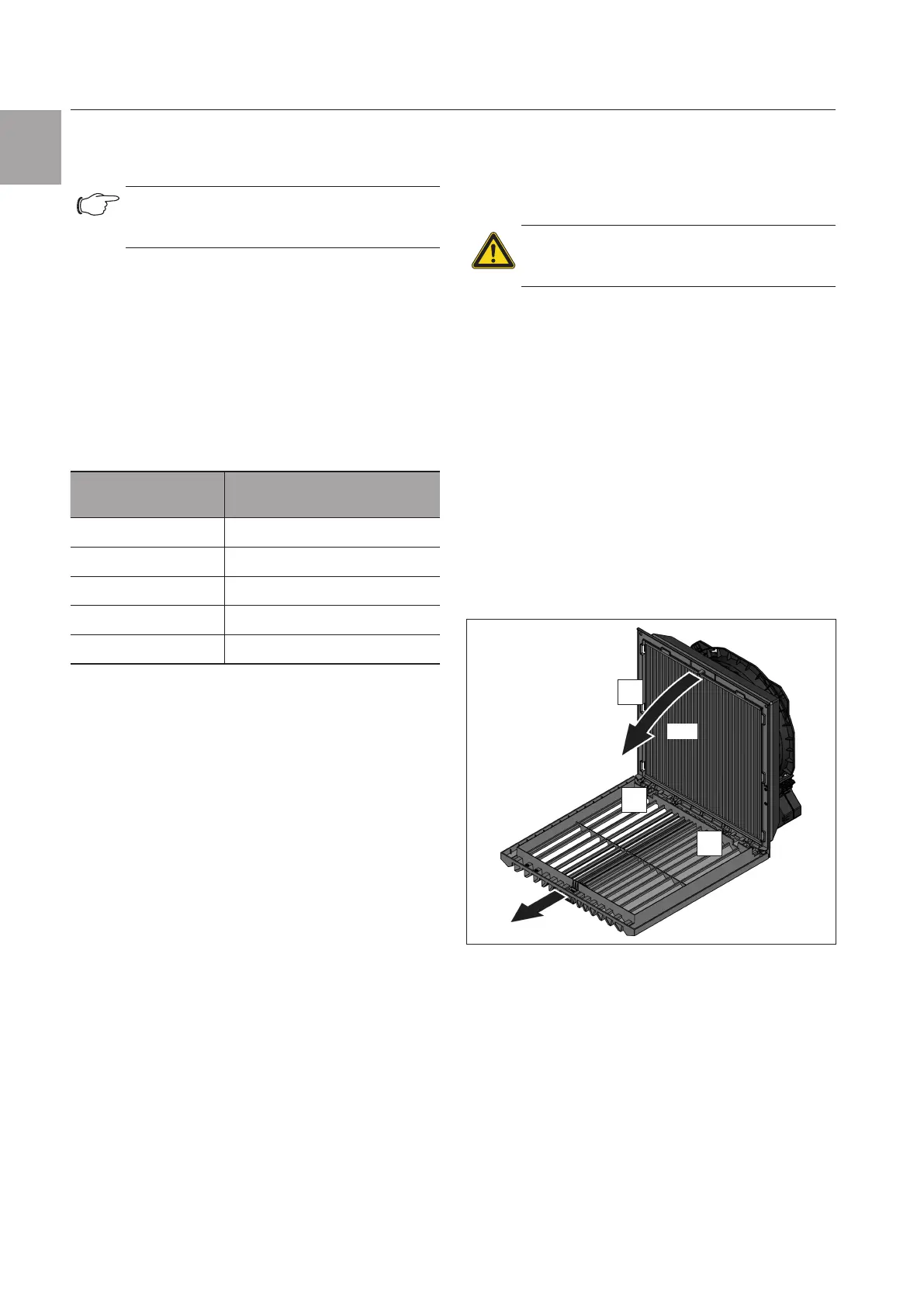
– To drill the lower holes, it is necessary to remove the
louvred grille as shown in fig.2. To do this, first loos-
en one hinge side and then the other.
1.
2.
90°
3.
Fig.2: Removing and mounting the louvred grille
– After screw-fastening the fan, the louvred grille must
be mounted again in the reverse sequence.
– If transporting, it is necessary that you screw-fasten
the fan to prevent it from falling out of the mounting
cut-out.
– The fan-and-filter unit is a rotating component that
may transfer vibrations and oscillations.
Appropriate measures to decouple vibration must be
taken in advance by the company responsible for the
overall plant or system.
– The protection category can be increased by means
of the following accessories:
– IP55 by using a pleated filter and absorber mat.